Vapor delivery system

a delivery system and vapor delivery technology, applied in chemical vapor deposition coatings, metal material coating processes, coatings, etc., can solve the problems of preventing the use of some otherwise desirable low vapor pressure liquid or solid precursor materials, and reducing the gas pressure of the vapor deposition system. , to achieve the effect of increasing the gas pressur

Inactive Publication Date: 2017-05-25
ULTRATECH INT INC
View PDF2 Cites 265 Cited by
  • Summary
  • Abstract
  • Description
  • Claims
  • Application Information

AI Technical Summary

Benefits of technology

[0015]A system controller in electrical communication with each of the controllable ALD pulse valve and the controllable inert gas flow valve is operable to pulse each of the controllable ALD pulse valve and the controllable inert gas flow valve. Each pulse includes opening the valve for a pulse duration ranging from 1 to 100 msec. While the ALD pulse valve is open precursor vapor flows out of the vapor space, through the ALD pulse valve and into the reaction chamber. While the controllable inert gas flow valve is open inert gas in the inert gas input line flows through the controllable inert gas flow valve and into the precursor container and is emitted below the fill level such that the inert gas bubbles up through the liquid or solid precursor to the vapor space provided above the fill line. The bubbling provides two benefits: to percolate through or evaporate the liquid or solid precursor material to collect or entrain precursor vapor in a vapor space above the fill level; and to increase the overall gas pressure in the container. The increase in overall pressure also increases the partial precursor vapor pressure in the vapor space.

Problems solved by technology

It is a typical problem in gas and or vapor phase depositions systems that vapor phase materials gleaned from liquid and solid precursor materials have a low vapor pressure, e.g. at room temperature or higher temperatures, which in some cases has prevented the use of some otherwise desirable low vapor pressure liquid or solid precursor materials.
While heating liquid and or solid precursor materials to provide a suitable vapor pressure for vapor deposition cycles is effective for some low vapor pressure precursor materials, there are upper temperature limits above which the precursor vapor is no longer suitable for vapor deposition cycles.
In particular most precursor vapor phase materials gleaned from liquid and or solid precursor materials have a breakdown temperature above which the precursor vapor is rendered ineffective or less effective for the desired gas deposition reaction.
In the specific example where vapor phase precursors are used in an Atomic Layer Deposition (ALD) reaction chamber, the breakdown temperatures of many desirable vapor phase precursor materials is between 75 and 150° C. such that any heating steps that heat the vapor phase precursor materials above 150° C. is not a viable solution for increasing precursor vapor pressure for ALD deposition cycles.
However this is not the case for ALD coating cycles.
As a result continuous flow bubbler systems are not suitable for ALD systems.
However Liu et al. disclose that the input conduit does not deliver the input gas pulses being injected into the sealed container below the level of precursor contained therein, but instead delivers input inert gas into the vapor space above the level of liquid and solid precursor contained within the precursor container.
One problem with this prior art configuration is that the inert gas pulse entering the precursor container fails to percolate through or evaporate the precursor material to collect or entrain precursor material.
Additionally, Liu et al. disclose a system that uses two pulse valves to generate a desirable input pulse which increases cost.
Moreover the vapor phase precursor material can be hazardous, flammable or both and therefore needs to be vented to a safe area.
While this safety feature is beneficial it adds complexity and cost.

Method used


Image

  • Vapor delivery system
  • Vapor delivery system
  • Vapor delivery system

Examples


Embodiment Construction

Exemplary System Architecture

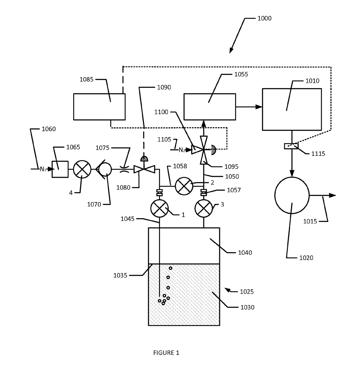
[0021]The present invention provides a simple and effective method to integrate a bubbled / flow-through low vapor pressure delivery (LVPD) system for Atomic Layer Deposition (ALD) systems. The hardware design eliminates the need for an MFC and a switching flow valve for redirecting the flow of the carrier gas with use of manual purge valves to allow safe purging of the precursor delivery lines which can be used for both solid and liquid precursor materials.

[0022]Referring now to FIG. 1 a non-limiting exemplary ALD system (1000) of the present invention is shown schematically. The ALD system (1000) includes a reaction chamber (1010) vented to an exhaust vent (1015) through a vacuum pump (1020). A single precursor container (1025) includes a liquid or solid precursor material (1030) filled to a fill level (1035) with a vapor space (1040) provided above the fill level (1035). Valves (1) (2) and (3) are manually operated valves. Valve (1) is disposed on an in...


PUM

PropertyMeasurementUnit
diameteraaaaaaaaaa
pressureaaaaaaaaaa
pressureaaaaaaaaaa

Abstract

An improved ALD system usable for low vapor pressure liquid and sold precursors. The ALD system includes a precursor container and inert gas delivery elements configured to increase precursor vapor pressure within a precursor container by injecting an inert gas pulse into the precursor container while a precursor pulse is being removed to the reaction chamber. A controllable inert gas flow valve and a flow restrictor are disposed along an inert gas input line leading into the precursor container below its fill level. A vapor space is provided above the fill level. An ALD pulse valve is disposed along a precursor vapor line extending between the vapor space and the reaction chamber. Both valves are pulsed simultaneously to synchronously remove precursor vapor from the vapor space and inject inert gas into the precursor container below the fill level.

Description

CROSS REFERENCE TO RELATED U.S. PATENT APPLICATIONS[0001]The present application claims priority under 35 U.S.C. §119(e) to provisional U.S. Patent Application Ser. No. 61 / 903,807 (Docket No. 3521.390) filed Jan. 23, 2013, which is incorporated herein by reference in its entirety and for all purposes.COPYRIGHT NOTICE[0002]A portion of the disclosure of this patent document may contain material that is subject to copyright protection. The copyright owner has no objection to the facsimile reproduction by anyone of the patent document or the patent disclosure, as it appears in the Patent and Trademark Office patent files or records, however otherwise reserves all copyright rights whatsoever. The following notice shall apply to this document: Copyright 2015 Ultratech Inc.BACKGROUND OF THE INVENTION[0003]a. Field of the Invention[0004]The present invention relates to a vapor deliver system operable to deliver precursor or reactant vapor pulses into a reaction chamber. In particular the i...

Claims


Application Information

Patent Timeline
Patent Type & Authority Applications(United States)
IPC IPC(8): C23C16/455C23C16/448C23C16/52
CPCC23C16/45544C23C16/45557C23C16/4482C23C16/52
Inventor BERTUCH, ADAMRUFFO, MICHAEL
Owner ULTRATECH INT INC
Why Eureka
Try Eureka