Mask Device for Optical Alignment and Equipment Thereof

a mask device and optical alignment technology, applied in the field of liquid crystal display, can solve the problems of affecting the quality of products, static electricity and particulates, etc., and achieve the effect of smoother change of the opening opening amount and increased display quality of products

Inactive Publication Date: 2017-05-25
TCL CHINA STAR OPTOELECTRONICS TECH CO LTD
View PDF1 Cites 3 Cited by
  • Summary
  • Abstract
  • Description
  • Claims
  • Application Information

AI Technical Summary

Benefits of technology

[0009]The technique problem solved by the disclosure is to provide a mask device for optical alignment and equipment thereof to achieve the curved (smooth) variation for the exposure amount of the openings of the overlapping regions of the two masks, to further eliminate the defects of the striped mura in the liquid crystal display and increase the display quality of the products.
[0051]The advantageous effect of the disclosure is that the device and the equipment of the disclosure comprises a first mask and a second mask partially overlapping with each other such that the first mask comprises a first overlapping region and a first non-overlapping region and the second mask comprises a second overlapping region and a second non-overlapping region, and the first overlapping region and the second overlapping region overlap with each other. In the meanwhile, the first overlapping region comprises a plurality of transmission openings arranged in a first direction; the first non-overlapping region comprises a plurality of transmission openings arranged in the first direction; the second overlapping region comprising a plurality of transmission openings arranged in the first direction; the second non-overlapping region comprises a plurality of transmission openings arranged in the first direction. Specifically, the openings of the first non-overlapping region and the openings of the second non-overlapping region are the same; the height Y1 of the openings of the first overlapping region satisfies Y1=H sin2(πX / 2L); the height Y2 of the openings of the second overlapping region satisfies Y2=H cos2(πX / 2L); wherein H is the height of the openings of the first non-overlapping region and the height of the openings of the second non-overlapping region; X=L−M; L is the length of the first overlapping region and the length of the second overlapping region; M is the distance between the first overlapping region and the second non-overlapping region or the distance between the second overlapping region and the second non-overlapping region. Compared with the current technology that the openings having linear variation in the overlapping regions of the plurality of masks for optical alignment, the disclosure configures the openings in the overlapping regions of the two masks to satisfy the curve variation of the trigonometric square such that the exposure amount of the openings changes smoother. In the overlapping regions, it satisfies H sin2(πX / 2L)+H cos2(πX / 2L)=H at the same position. That is the exposure amount of the openings of the overlapping regions and the exposure amount of the openings of the non-overlapping regions is the same after the two masks overlap with each other such that the display effects are uniform in the liquid crystal display device. In the meanwhile, the openings of curved variation may eliminate the defects of the stripped mura in the liquid crystal display device to increase the display quality of the products.

Problems solved by technology

The friction alignment method would produce static electricity and particulate pollution.
That is the corresponding exposure amount is also linear variation such that the defects of stripped mura occur in the display panel to impede the quality of the product.

Method used


Image

  • Mask Device for Optical Alignment and Equipment Thereof
  • Mask Device for Optical Alignment and Equipment Thereof
  • Mask Device for Optical Alignment and Equipment Thereof

Examples


first embodiment

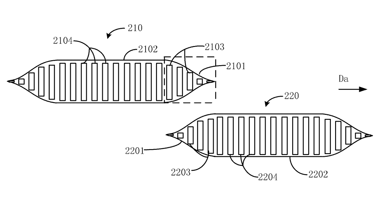
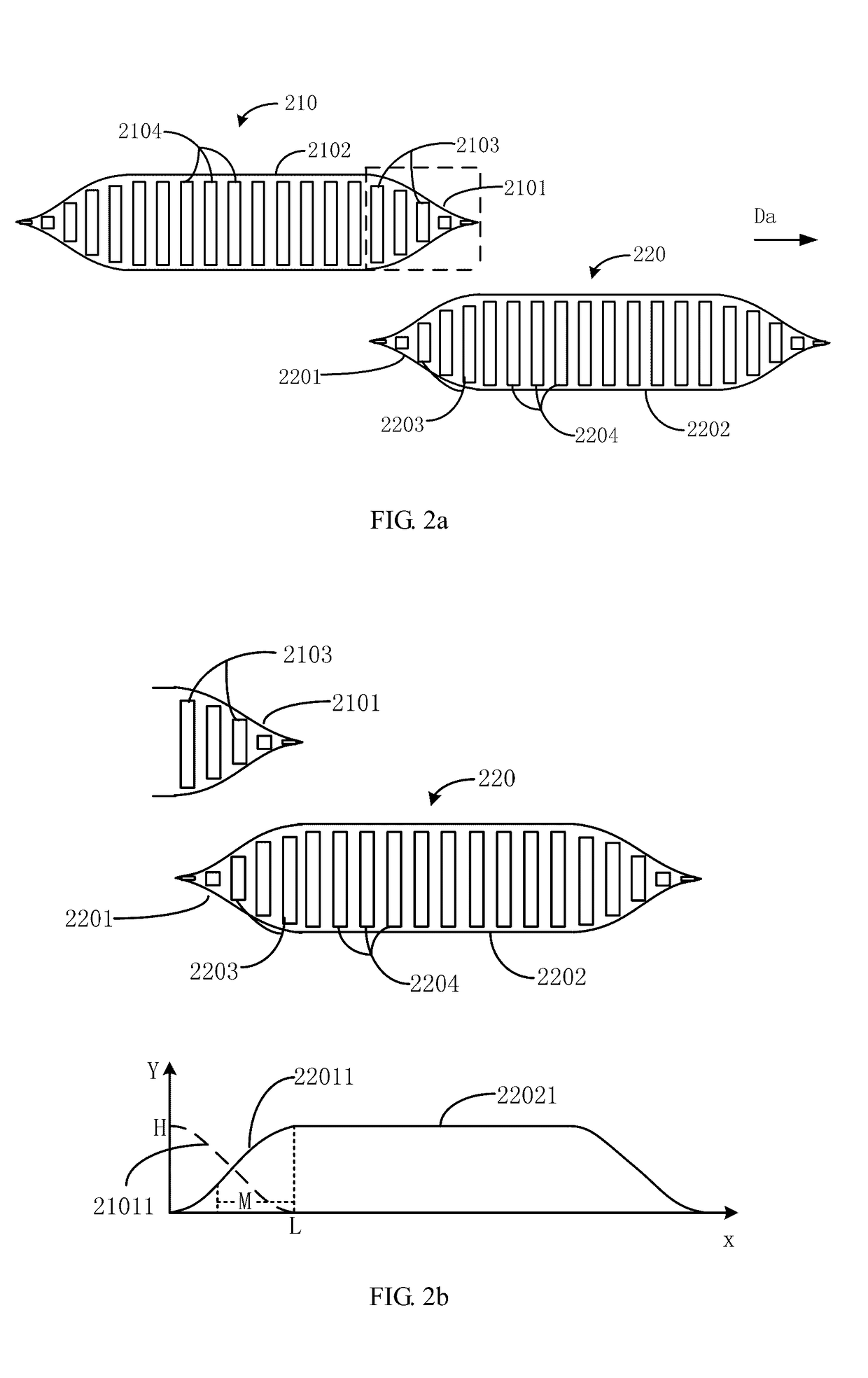
[0065]Refer to FIG. 2a and FIG. 2b. FIG. 2a is the schematic view of the mask device for optical alignment according to the disclosure. FIG. 2b is the schematic view showing the height variation of the openings of the overlapping regions of the two masks in FIG. 2a.

[0066]The mask device 20 comprises:

[0067]a first mask 210 and a second mask 220;

[0068]the first mask 210 comprises a first overlapping region 2101 and a first non-overlapping region 2102;

[0069]the second mask 220 comprises a second overlapping region 2201 and a second non-overlapping region 2202;

[0070]the first overlapping region 2101 and the second overlapping region 2201 overlap with each other;

[0071]the first overlapping region 2101 comprises a plurality of transmission openings 2103 arranged in a first direction Da;

[0072]the first non-overlapping region 2102 comprises a plurality of transmission openings 2104 arranged in the first direction Da;

[0073]the second overlapping region 2201 comprising a plurality of transmi...

second embodiment

[0095]Refer to FIG. 3a for the schematic view of the mask device for optical alignment according to the disclosure. The mask device 30 comprises:

[0096]a first mask 310 and a second mask 320;

[0097]the first mask 310 comprises a first overlapping region 3101 and a first non-overlapping region 3102;

[0098]the second mask 320 comprises a second overlapping region 3201 and a second non-overlapping region 3202;

[0099]the first overlapping region 3101 and the second overlapping region 3201 overlap with each other;

[0100]the first overlapping region 3101 comprises a plurality of transmission openings 3103 arranged in a first direction Da;

[0101]the first non-overlapping region 3102 comprises a plurality of transmission openings 3104 arranged in the first direction Da;

[0102]the second overlapping region 3201 comprising a plurality of transmission openings 3203 arranged in the first direction Da;

[0103]the second non-overlapping region 3201 comprises a plurality of transmission openings 3204 arran...

third embodiment

[0123]Refer to FIG. 4 for the schematic view of the exposure equipment for optical alignment according to the disclosure.

[0124]The exposure equipment comprises the mask device 410 as the first or the second embodiment mentioned above, a first light source 420 and a second light source 430.

[0125]The first light source 420 provides light for the openings of the first mask 411.

[0126]The second light source 430 provides light for the openings of the second mask 412.

[0127]The configuration of the first light source 420 and the second light source 430 is the same as the current configuration of the existing exposure equipment. The light source may be configured at the side surfaces of the exposure equipment and may be irradiated onto the first mask 411 and the second mask 412 under different angles by a plurality of reflective mirrors and polarizers.

[0128]In other embodiment, only one light source may be selected. The light may be irradiated onto the first mask 410 and the second mask 420...


PUM

PropertyMeasurementUnit
angleaaaaaaaaaa
optical alignmentaaaaaaaaaa
height Y1aaaaaaaaaa

Abstract

A mask device for optical alignment and equipment thereof are disclosed. The mask device comprises a first mask having a first overlapping region and a first non-overlapping region and a second mask having a second overlapping region and a second non-overlapping region. The first and second mask overlap with each other. The first overlapping and non-overlapping regions, the second overlapping and non-overlapping regions comprise openings respectively. The height of the openings of the first and the second overlapping region are arranged to vary according the trigonometric square such that the height of the openings at the same position that the overlapping regions overlap with each other is the same as that the openings of the first or the second non-overlapping regions. Compared with the current technology, the disclosure may eliminate the defects of the striped mura in the liquid crystal display to increase the display quality of the products.

Description

BACKGROUND[0001]Technical Field[0002]The disclosure is related to the technology field of the liquid crystal display, and more particular to a mask device for optical alignment and equipment thereof.[0003]Related Art[0004]By applying an electric field to the field generating electrode of the upper and the lower display panel, the liquid crystal of the liquid crystal layer in the liquid crystal device deflects under the influence of the electric field. Therefore, the image display can be achieved by controlling the polarized light incident to the liquid crystal layer. Currently, vertical alignment (VA, vertical alignment) mode liquid crystal display has been widely studied and applied because of its high contrast and wide viewing angle standard.[0005]In the production process of the liquid crystal display, the friction alignment and the optical alignment are often used. The friction alignment method would produce static electricity and particulate pollution. The optical alignment met...

Claims


Application Information

Patent Timeline
Patent Type & Authority Applications(United States)
IPC IPC(8): G02F1/13G03F7/20G02F1/1337
CPCG02F1/1303G03F7/2045G02F1/133788
Inventor HAN, BINGSHIH, MING-HUNGLI, MENG
Owner TCL CHINA STAR OPTOELECTRONICS TECH CO LTD
Why Eureka
Try Eureka