Machine and a Method for Additive Manufacturing with Continuous Fiber Reinforcements

a technology of continuous fiber reinforcement and machine, applied in the direction of additive manufacturing with liquids, manufacturing tools, manufacturing processes, etc., can solve the problems of wasting material and energy, reducing the strength of discontinuous fibers, and adding time to the build

Inactive Publication Date: 2017-06-01
UT BATTELLE LLC
View PDF8 Cites 142 Cited by
  • Summary
  • Abstract
  • Description
  • Claims
  • Application Information

AI Technical Summary

Problems solved by technology

The creation and removal of support structures wastes material and energy and adds time to the build.
While building parts of discontinuous fiber reinforced feed stock provides significant advantages in terms of room temperature processing and dimensional stability, the discontinuous fibers are limited in terms of strength and still require a sacrificial structure for supporting cantilevered or arched features.

Method used


Image

  • Machine and a Method for Additive Manufacturing with Continuous Fiber Reinforcements
  • Machine and a Method for Additive Manufacturing with Continuous Fiber Reinforcements
  • Machine and a Method for Additive Manufacturing with Continuous Fiber Reinforcements

Examples


Embodiment Construction

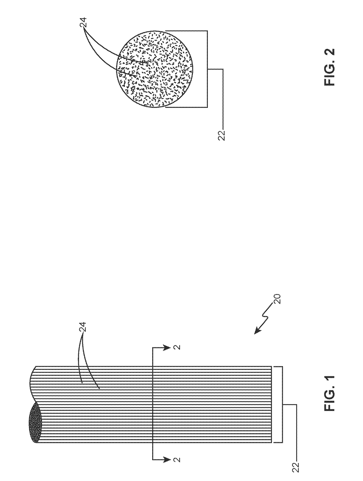
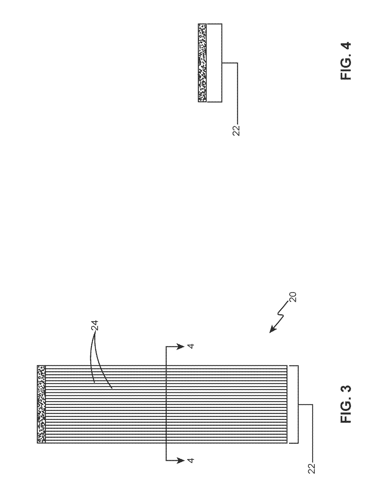
[0033]With reference first to FIGS. 1-4, two examples of dry continuous fiber reinforcements 20 will now be described in detail. The terms “continuous fiber reinforcements” encompass fiber reinforcements that are uncut, which provide a considerable strength advantage over chopped fibers. In these examples, a tow 22 or bundle of unidirectional (shown), multidirectional or woven filaments 24 may be round-shaped (FIGS. 1-2), ribbon-shaped (FIGS. 3-4), or otherwise shaped. The individual filaments 24 may be made from carbon, glass, aramid or other materials having diameters of approximately 5 to 10 micrometers. Depending on the size and strength requirements of the final part, filament 24 counts can be approximately 2,000-50,000, although lower or higher counts may also be used. These examples illustrate dry tows 22, since no additional material is present in the continuous fiber reinforcements 20.

[0034]Referring now to FIGS. 5-6, an example of continuous fiber reinforcement 20 that is ...


PUM

PropertyMeasurementUnit
diametersaaaaaaaaaa
lengthaaaaaaaaaa
temperatureaaaaaaaaaa

Abstract

Several examples of additive manufacturing machines and methods for depositing a bead of composite polymer material having continuous fiber reinforcement are disclosed. A length of fiber reinforcement is provided to a nozzle. The fiber reinforcement is embedded into a stream of a base polymer material at the nozzle and deposited as a bead of composite polymer material having fiber reinforcement. The fiber reinforcement may be dry or pre-impregnated with a reinforcing polymer. The additional strength of the composite polymer material having fiber reinforcement allows for true, three-dimensional printing of articles having unsupported regions.

Description

CROSS-REFERENCE TO RELATED APPLICATIONS[0001]This patent application is related to U.S. Nonprovisional patent application Ser. No. ______, entitled “An Article Made by Additive Manufacturing with Continuous Fiber Reinforcements”, filed concurrently, which is incorporated herein by reference in its entirety.STATEMENT REGARDING FEDERALLY SPONSORED RESEARCH AND DEVELOPMENT[0002]This invention was made with government support under Contract No. DE-AC05-000R22725 awarded by the U.S. Department of Energy. The government has certain rights in the invention.THE NAMES OF THE PARTIES TO A JOINT RESEARCH AGREEMENT[0003]None.INCORPORATION-BY-REFERENCE OF MATERIAL SUBMITTED ON A COMPACT DISC OR AS A TEXT FILE VIA THE OFFICE ELECTRONIC FILING SYSTEM (EFS-WEB)[0004]None.STATEMENT REGARDING PRIOR DISCLOSURES BY THE INVENTOR OR A JOINT INVENTOR[0005]None.BACKGROUND OF THE INVENTION[0006]1. Field of the Invention[0007]The present disclosure relates to polymer additive manufacturing and more specifica...

Claims


Application Information

Patent Timeline
Patent Type & Authority Applications(United States)
IPC IPC(8): B29C67/00
CPCB29C67/0096B33Y10/00B33Y30/00B29L2031/00B29K2077/10B29K2307/04B29K2309/08B33Y50/02B29C70/222B29C64/118B29C64/106B29C64/209B29C64/295
Inventor KUNC, VLASTIMILBLUE, CRAIG A.DUTY, CHAD E.LIND, RANDALL F.LINDAHL, JOHN M.LLOYD, PETER D.LOVE, LONNIE J.LOVE, MATTHEW R.POST, BRIAN K.RIOS, ORLANDO
Owner UT BATTELLE LLC
Why Eureka
Try Eureka