Pressure detection device

a detection device and pressure technology, applied in measurement devices, rapid change measurement, instruments, etc., can solve the problems of significant lowering of detection accuracy, degrading of s/n ratio in output signal, and difficult removal of detection with filter circuits, so as to facilitate maintenance, reduce noise components, and high accuracy pressure detection

Active Publication Date: 2017-06-01
CITIZEN WATCH CO LTD +1
View PDF2 Cites 11 Cited by
  • Summary
  • Abstract
  • Description
  • Claims
  • Application Information

AI Technical Summary

Benefits of technology

[0017]In the pressure detection device 10 configured as described above and according to the present invention, the following remarkable effects are provided.
[0018](1) Since the processing circuit 30 includes the voltage transformation circuit 35 which only transforms the power supply voltage Vdd fed from an external power supply so as to obtain the first reference voltage Vr1 with a predetermined voltage value, the integrator circuit 31 which uses the first reference voltage Vr1 as the operation reference to perform integral processing on the detection signal Qi so as to convert the detection signal Qi into a voltage waveform, and at least one or more amplifier circuits 32 which use the second reference voltage Vr2 with a predetermined voltage value as the operation reference to perform amplification processing on the output signal Vout1 from the integrator circuit 31, the noise component caused by a disturbance is simultaneously superimposed both on the first reference voltage Vr1 and the detection signal Qi. Hence, in the configuration in which the noise components cancel each other out, it is possible to reduce the noise component which is superimposed on the necessary signal, and thus it is possible to realize highly accurate pressure detection. Moreover, since a complicated digital device such as a computer is not needed for noise removal, it is possible to perform the operation at a low cost, and it is also possible to facilitate maintenance and to further reduce the size and weight.
[0019](2) In a preferred aspect, the voltage transformation circuit 35 is formed with the voltage dividing resistor circuit in which a plurality of voltage dividing resistors R1 and R2 are combined, and thus it is possible to perform the operation with a simple circuit configuration and to prevent a stabilization circuit such as a regulator from being needed, with the result that it is possible to more easily perform the operation at a lower cost.
[0020](3) In a preferred aspect, when the integrator circuit

Problems solved by technology

As described above, disadvantageously, when a noise component enters the charge signal Qi serving as the detection signal in a mixed manner, the processing circuit 100 in the pressure detection device also amplifies such a noise component, and thus an S/N ratio in the output signal is degraded, and the accuracy of the detection is significantly lowered.
As a method of removing the noise component N02 in the output signal Vout02, providing a filter circuit in a stage subsequent to the

Method used


Image

  • Pressure detection device
  • Pressure detection device
  • Pressure detection device

Examples


first embodiment

[0046]The configuration of the pressure detection device 10 according to the first embodiment will first be specifically described with reference to FIGS. 3 to 6.

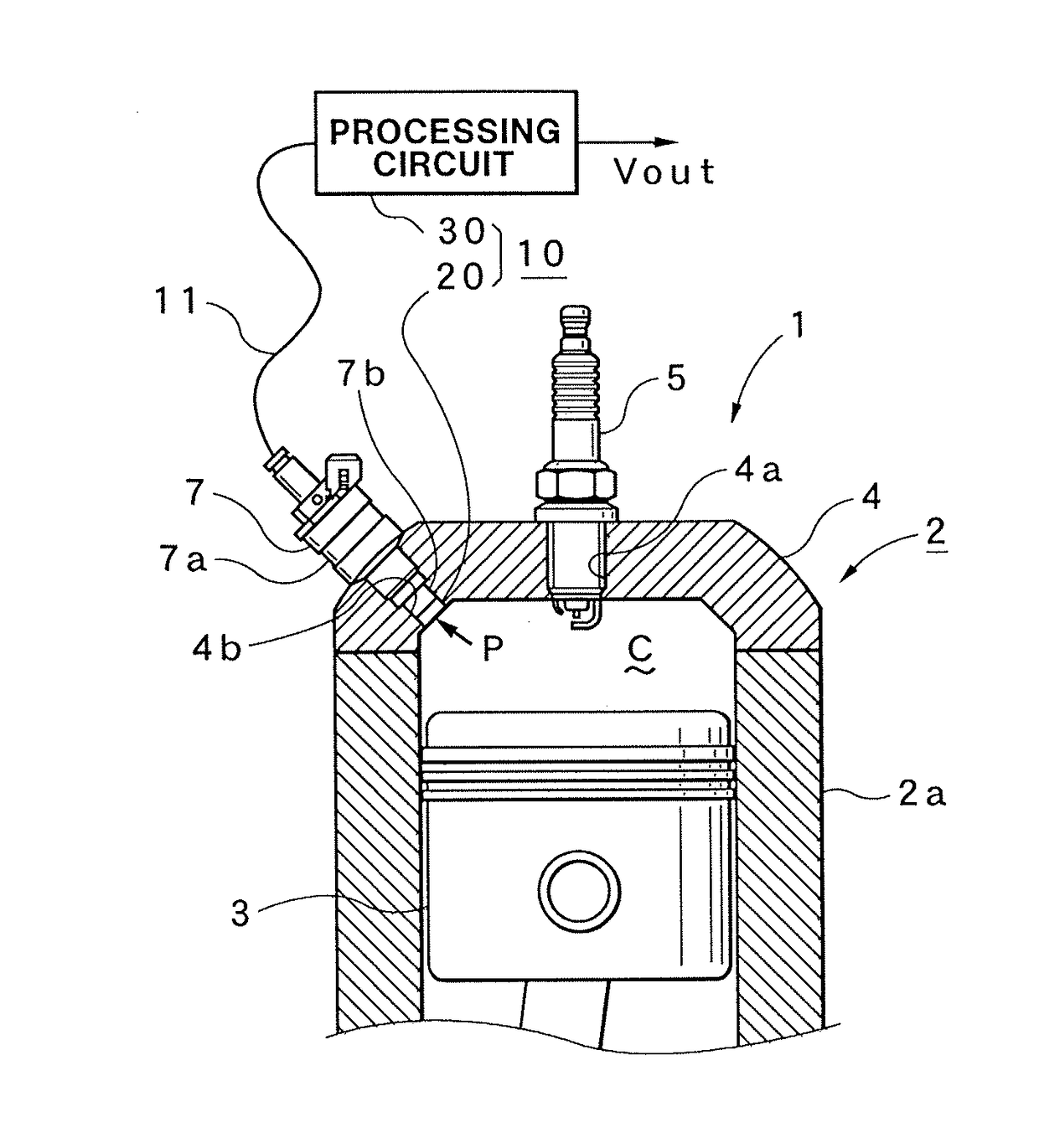
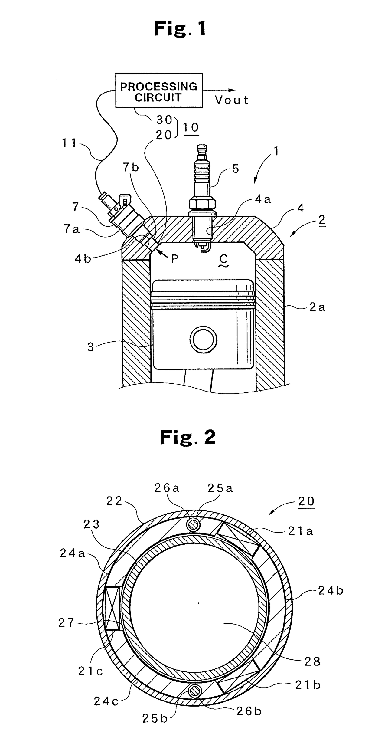
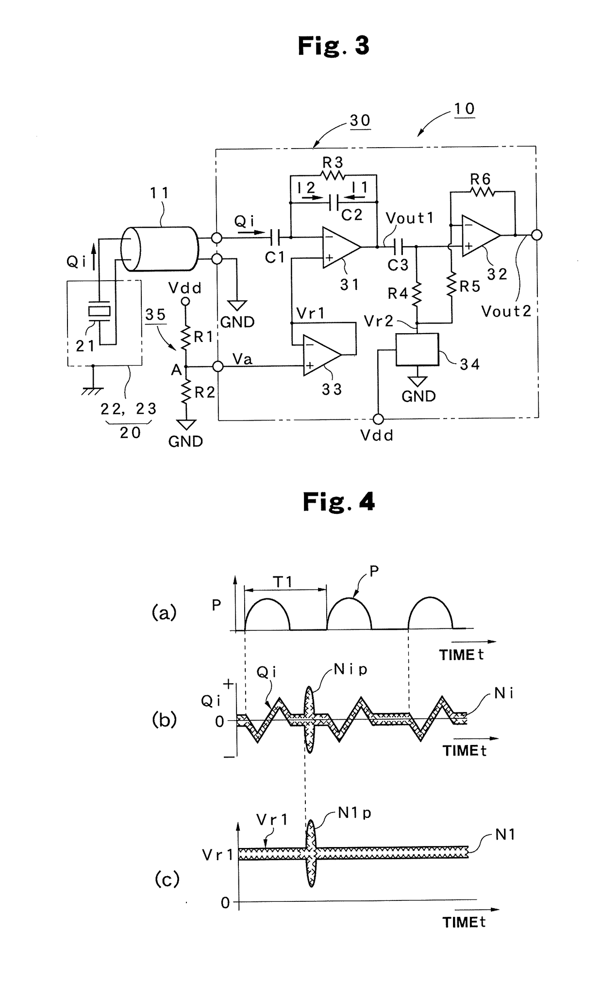
[0047]As shown in FIG. 3, the pressure detection device 10 includes the detection portion 20 and the processing circuit 30, and as described previously, the detection portion 20 includes a piezoelectric element 21 for detecting the combustion pressure P of the engine 1 (see FIG. 1) and the piezoelectric element 21 is covered with a conductive enclosure (indicated by broken lines) of the front outer enclosure 22 and the front inner enclosure 23. The charge signal Qi which is the detection signal from the piezoelectric element 21 is fed through the conductive portion 11 to the processing circuit 30. In other words, one terminal of the piezoelectric element 21 is connected through the conductive portion 11 to the processing circuit 30, and the other terminal is connected through the conductive portion 11 to the GND of the proc...

second embodiment

[0067]A pressure detection device 50 according to a second embodiment will then be described with reference to FIG. 7. The pressure detection device 50 shown in FIG. 7 includes the detection portion 20 and a processing portion 60 as in the first embodiment shown in FIG. 3. Since the detection portion 20 is the same as that in the first embodiment shown in FIG. 3, the same portions are identified with the same numbers, and thus a detailed description thereof will be omitted. Since the illustrated processing portion 60 is formed with a one-chip integrated circuit, and the basic configuration thereof is the same as that of the processing circuit 30 in the first embodiment shown in FIG. 3, the same portions except some components are identified with the same numbers, and thus a detailed description thereof will be omitted. The processing portion 60 includes, as in the first embodiment, the three operational amplifiers 31, 32 and 33 which are operated with a single power supply and the s...

third embodiment

[0072]A pressure detection device 70 according to a third embodiment will then be described with reference to FIG. 8. The pressure detection device 70 shown in FIG. 8 includes the detection portion 20 and a processing portion 80 as in the first embodiment shown in FIG. 3. In FIG. 8, the pressure detection device 70 of the third embodiment includes the detection portion 20 and the processing portion 80 as in the first embodiment. Since the detection portion 20 is the same as that in the first embodiment, the same portions are identified with the same numbers, and thus a detailed description thereof will be omitted. In the configuration of the processing portion 80, the same components as those in the processing circuit 30 of the first embodiment (see FIG. 3) are identified with the same numbers, and thus a detailed description thereof will be omitted.

[0073]In this case, the processing portion 80 includes, as in the first embodiment, the three operational amplifiers 31, 32 and 33 whic...


PUM


Abstract

There is provided a pressure detection device including: a pressure detection element which receives pressure so as to output a detection signal corresponding to the pressure P; and a processing circuit which processes and outputs the detection signal output from the pressure detection element, where the processing circuit includes: a voltage transformation circuit which only transforms a power supply voltage fed from an external power supply so as to obtain a first reference voltage with a predetermined voltage value; an integrator circuit which uses the first reference voltage as an operation reference to perform integral processing on the detection signal so as to convert the detection signal into a voltage waveform; and at least one or more amplifier circuits which use a second reference voltage with a predetermined voltage value as an operation reference to perform amplification processing on an output signal from the integrator circuit.

Description

TECHNICAL FIELD[0001]The present invention relates to a pressure detection device which is suitably used when pressure such as the combustion pressure of an engine is detected.BACKGROUND ART[0002]In general, various detection devices are proposed which detect physical quantity such as pressure and magnetism and convert them into electrical signals. Since in such a detection device, a sensor outputs a variation in the physical amount as a differential value, the detection device includes a processing circuit for converting, by integration with an integrator circuit, a detection signal from the sensor into the voltage of a waveform similar to the variation in the physical amount.[0003]FIG. 9 shows an example of a processing circuit in a pressure detection device which detects, as a physical amount, the combustion pressure of an engine. The processing circuit 100 shown in FIG. 9 is formed with two operational amplifiers 104 and 110 which are an integrator circuit that integrates a dete...

Claims


Application Information

Patent Timeline
IPC IPC(8): G01L23/22G01L23/10
CPCG01L23/222G01L23/225G01L23/10
Inventor YOMOYAMA, MASANORI
Owner CITIZEN WATCH CO LTD
Why Eureka
Try Eureka