Occluder and Occlusion Device

a technology of occlusion device and occluder, which is applied in the field of interventional medical devices, can solve problems affecting the occlusion effect, and achieve the effects of high locking reliability, simple structure and simplified preparation process and locking operation

Active Publication Date: 2017-06-08
LIFETECH SCIENTIFIC (SHENZHEN) CO LTD
View PDF4 Cites 12 Cited by
  • Summary
  • Abstract
  • Description
  • Claims
  • Application Information

AI Technical Summary

Benefits of technology

[0016]In the occluder of the present invention, a locking process may be carried out with a locking member and a stopping member being coupled with a proximal hub having a locking hole; with a simple structure, the occluder simplifies the preparation process and locking operation. Moreover, the stopping members with slightly larger radial size press against the end face of the proximal hub to achieve locking, the locking reliability is high, and occurrences of locking failure are minimized. At least one of the proximal hub and the stopping member is an elastic member, the stopping members with slightly larger radial size pass through the locking hole by elastic deformations, which is a reversible operating process, and both the locking process and the withdrawing process are simple and easy.
[0017]In the occlusion device of the present invention, the traction member is detachably connected to the locking member of the above-mentioned occluder, the traction member is able to facilitate controlling the connection or releasing the connection, which increases the operability of the connection of the traction member and the occluder, and after the locking is completed, the occlusion device can be released from the connection and be evacuated out of the body, thereby reducing residues in vivo. Meanwhile, the traction member is not required to pass through the distal end of the occluder, which can avoid damage to cardiac tissues, reduce the time of an occlusion procedure, and increase the efficiency of an operation at the same time. Moreover, as the locking member is only fixed with the distal end of the occlusion body and the placement direction of the locking member is the same as that of the sheathing tube, the structure and the fixing mode of the locking member do not affect the deformation of the occluder in the delivery sheath tube and the occlusion to the defect site after the occluder is pushed in place. The size of the sheath tube only needs to fit the size of the occluder. In addition, since the size of the sheathing tube is not increased, this is more beneficial for the surgical procedure.

Problems solved by technology

The shape memory metals may cause fatigue failure in use, while the polymer materials have the characteristics of low elasticity or inelasticity, which will lead to insufficient contraction force between the two occlusion units as well as the inability of fitting either side of the defect site, thereby affecting the occluding effect.

Method used


Image

  • Occluder and Occlusion Device
  • Occluder and Occlusion Device
  • Occluder and Occlusion Device

Examples


first embodiment

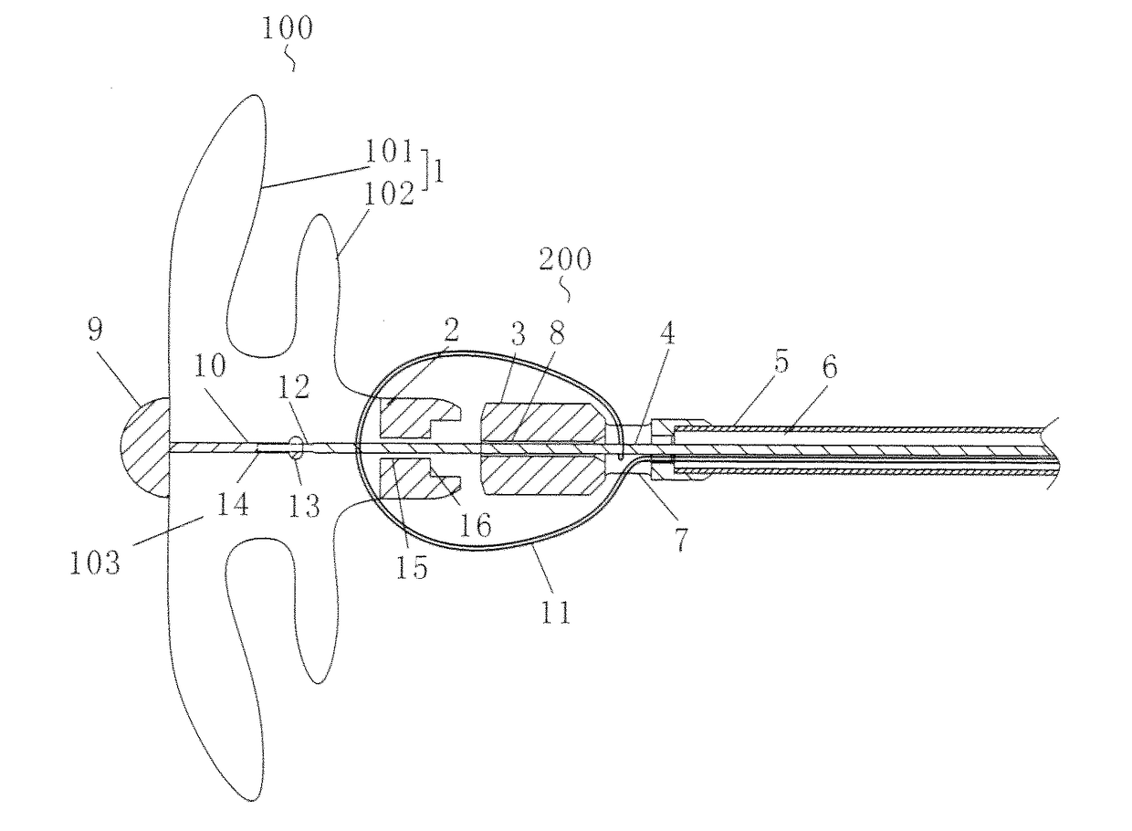
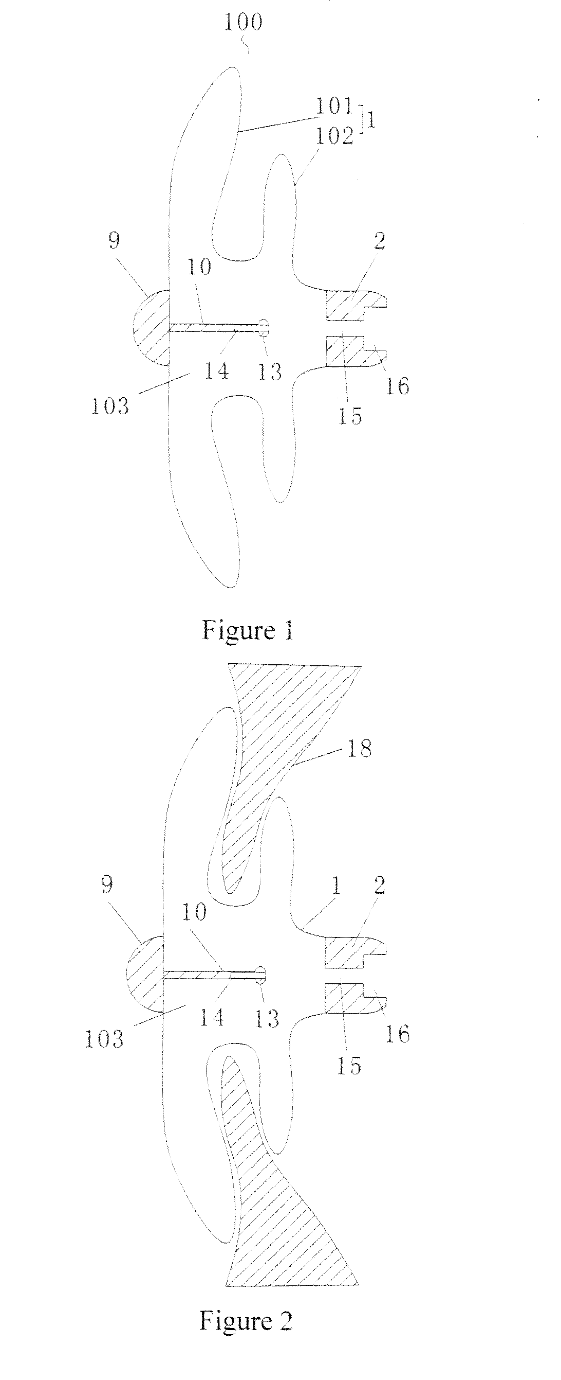
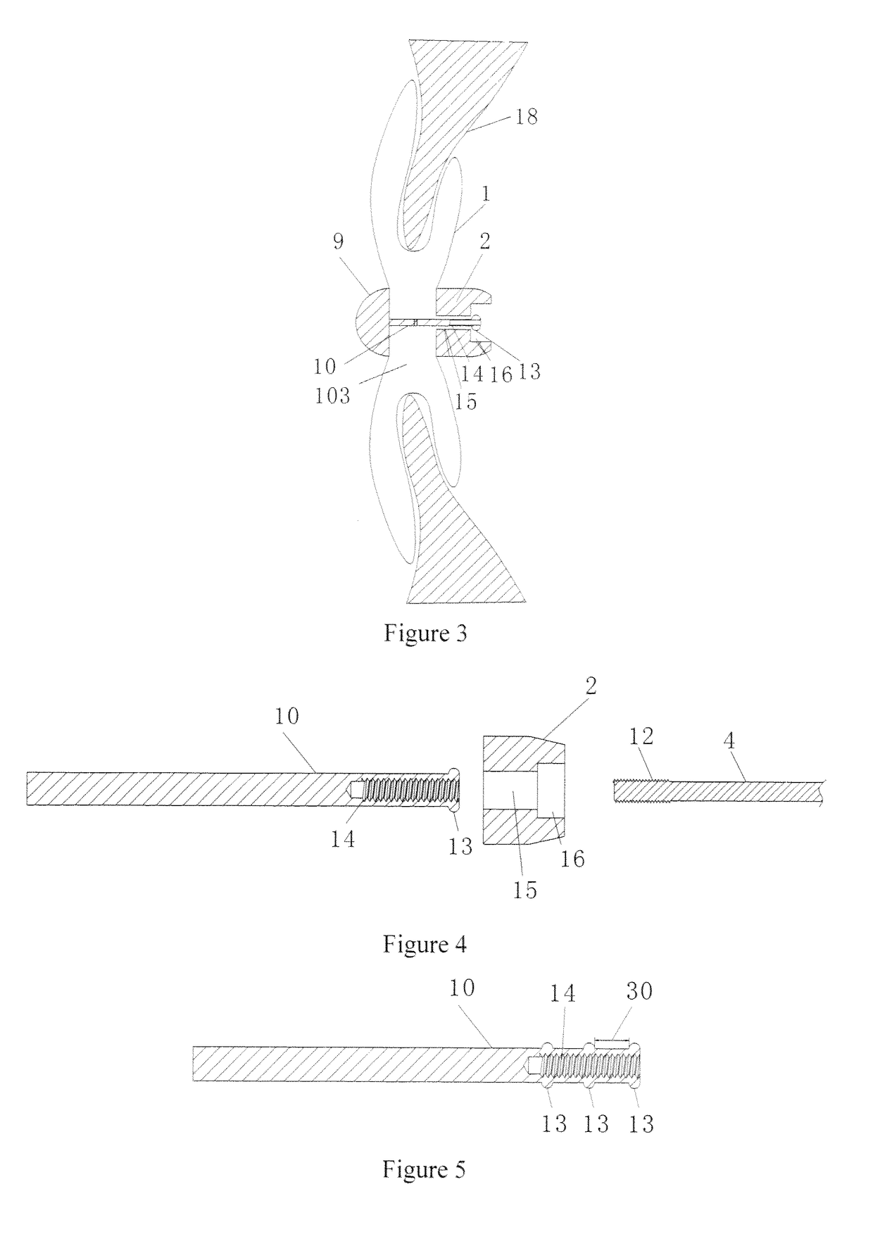
[0040]In the first embodiment, as shown in FIGS. 1-3, the occluder 100 comprises a meshed occlusion body 1 provided with a cavity 103, and a proximal hub 2. The occluder 100 further comprises a locking member 10 and a stopping member 13 both of which are disposed in the cavity 103, wherein the distal end of the locking member 10 is connected with a distal end of the occlusion body 1, and the stopping member 13 is disposed at a proximal end of the locking member 10. The proximal hub 2 is provided with a locking hole 15 penetrating through the cavity 103. The radial size of the stopping member 13 is slightly larger than an aperture of the locking hole 15. The radial size of the locking member 10 is smaller than an aperture of the locking hole 15, and at least one of the proximal hub 2 and the stopping member 13 is an elastic member. The elastic member can undergo resilient deformation under external force, and can completely recover from the deformation after the external force disapp...

second embodiment

[0059]In the second embodiment, as shown in FIG. 9, the occlusion device comprises the occluder 100, a hollow delivery mechanism 200, and the traction member 4 movably accommodated in the delivery mechanism 200. The distal end of the traction member 4 extends through the distal end of the delivery mechanism 200 and is detachably connected with the proximal end of the locking member 10 in the cavity 103. The traction member 4 can utilize traction on the locking member 10 to drive the distal end of the occluder 100 to move towards the proximal end under external force by an operator, for example a surgeon, until the stopping members 13 extend through the locking hole 15 and then press against the end face of the proximal hub 2 to lock the occluder 100.

[0060]Referring to FIGS. 9 and 10, in one implementation, the hollow delivery mechanism 200 comprises a delivery tube 5, and the delivery tube 5 is axially provided with a lumen 6 that communicates with the outside at least at the distal...


PUM


Abstract

The present invention relates to an occluder (100), comprising a meshed occlusion body (I) provided with a cavity (103), and a proximal hub (2), as well as a locking member (10) and a stopping member (13) both of which are located in the cavity (103). The distal end of the locking member (10) is connected to the distal end of the occlusion body (1). The stopping member (13) is disposed at the proximal end of the locking member (10). The proximal occluder head (2) is provided with a locking hole (15) in communication with the cavity (103). The radial size of the stopping member (13) is slightly larger than the diameter of the locking hole (15). The radial size of the locking member (10) is smaller than the diameter of the locking hole (15), and at least one of the proximal occluder head (2) and the stopping member (13) is an elastic member. An occlusion device comprises the occluder (100), a hollow delivery mechanism (200) and a traction member (4). The distal end of the traction member (4) is detachably connected to the proximal end of the locking member (10) of the occluder (100) after extending through the distal end of the delivery mechanism (200). The occlusion device has a simple locking structure, and simplifies the manufacturing process and the locking operation.

Description

TECHNICAL FIELD[0001]The present invention relates to an interventional medical device, and more particularly to an occluder and occlusion device for the interventional treatment of congenital heart defect.BACKGROUND ART[0002]Percutaneous interventional technology is a rapidly developed means of disease treatment in recent years, and its application range is becoming wider and wider. A variety of materials, devices and drugs can be placed into heart, artery and vein blood vessels of a human body by using catheter interventional therapy, wherein the devices may be heart defect occluders, vascular plugs, vascular filters, etc.[0003]The transcatheter interventional occluder is a commonly used device in transcatheter interventional therapy and can be used for the minimally invasive treatment of such congenital heart diseases as atrial septal defects and ventricular septal defects, patent ductus arteriosus and patent foramen ovale. An occluder in the prior art typically comprises an occl...

Claims


Application Information

Patent Timeline
Patent Type & Authority Applications(United States)
IPC IPC(8): A61F2/94A61F2/966A61F2/86
CPCA61F2/94A61F2002/9505A61F2/966A61F2/86A61B17/0057A61B2017/00831A61B2017/00606A61B2017/00619A61B2017/00575A61F2/02A61B2017/00623A61B2017/00243A61B2017/00862A61B17/00A61B17/12168A61B17/12172A61B2017/12095
Inventor LIU, XIANGDONGCHEN, XIANMIAOFU, XIANGCHEN, JIE
Owner LIFETECH SCIENTIFIC (SHENZHEN) CO LTD
Why Eureka
Try Eureka