Evaporator

a technology of evaporator and evaporator body, which is applied in the direction of indirect heat exchangers, lighting and heating apparatus, transportation and packaging, etc., can solve the problems of reducing the thermal performance of the evaporator b>80/b>, reducing the comfort of users, and being more serious. , to achieve the effect of maximizing heat exchange efficiency, reducing temperature variation, and maintaining the comfort of passengers

Active Publication Date: 2017-06-08
HANON SYST
View PDF9 Cites 6 Cited by
  • Summary
  • Abstract
  • Description
  • Claims
  • Application Information

AI Technical Summary

Benefits of technology

[0013]That is, the evaporator according to the present invention has 8-pass flow from the first area to the eighth area so as to uniformly distribute the refrigerant to each of the areas, thereby reducing temperature variation. Therefore, according to the evaporator of the present invention, it is possible to maximize the heat exchange efficiency with respect to outdoor air. In addition, the air discharged to the left and right sides in a vehicle room can have uniform temperature distribution, thereby maintaining the comfort of passengers.
[0014]Furthermore, the evaporator has the plurality of tubes, of which flow paths respectively have the same flow path area and the same full circumference length and which have a hydraulic diameter in the range of 1.0 to 2.8 mm, and the core part, of which width is 150 to 300 mm. Therefore, the evaporator of the present invention has advantages of improving thermal performance while reducing temperature variation.
[0015]In addition, the number of the tubes forming the first area and the number of the tubes forming the eighth area are the same as each other, the number of the tubes forming the second area and the number of the tubes forming the seventh area are the same as each other, the number of the tubes forming the third area and the number of the tubes forming the sixth area are the same as each other, and the number of the tubes forming the fourth area and the number of the tubes forming the fifth area are the same as each other, such that the baffles are provided at the same positions so as to be symmetrical to each other in the width direction and, thus, the manufacturing process can be simplified.
[0016]Also, the first header tank and the second header tank respectively have the same number of the baffles, which are located in the first line and the second line, wherein the baffles located in the first line and the second line of the first header tank and the second header tank respectively have the same positions in the lengthwise direction, thereby further improving manufacturability.
[0017]Herein, the evaporator has the same number of tubes which form the opposite areas of the first line and the second line, wherein it is possible to form the evaporator in such a manner that the number of the tubes of the eighth area is smaller than or equal to the number of the tubes of the seventh area and the number of the tubes of the seventh area is smaller than or equal to the number of the tubes of the sixth area. In other words, according to the evaporator of the present invention, the number of the tubes forming an area, which is adjacent to an outlet, is smaller than or equal to the number of the tubes forming neighboring areas such that the concentration of the refrigerant on the area adjacent to the outlet can be prevented.
[0018]Therefore, the evaporator according to the present invention has 8-pass flow from the first area to the eighth area so as to uniformly distribute refrigerant to each of the areas, thereby reducing temperature variation and maximizing the heat exchange efficiency with respect to outdoor air, and also has an advantage of uniform temperature distribution in the air discharged to the right and left sides in a vehicle room, thereby maintaining the comfort of passengers.

Problems solved by technology

As described above, if the refrigerant distribution in the evaporator 80 is non-uniform, the thermal performance of the evaporator 80 becomes decreased and thus a temperature difference is generated in the air discharged to the left and right sides in the vehicle room, thereby decreasing the temperature comfort of users.
The problems as described above become more serious when the amount of the refrigerant in the evaporator becomes decreased and thus the flow rate thereof becomes low.

Method used


Image

  • Evaporator
  • Evaporator
  • Evaporator

Examples


Embodiment Construction

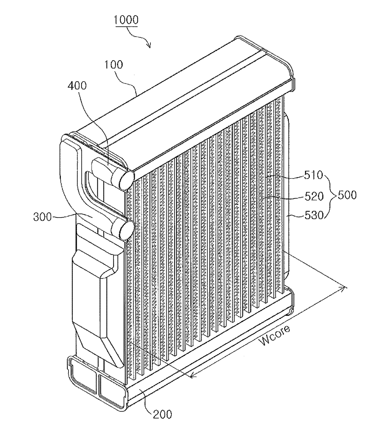
[0032]Hereinafter, an evaporator having the above-mentioned features according to the preferred embodiments of the present invention will be described in detail with reference to the attached drawings.

[0033]FIG. 5 is a perspective view for showing an evaporator 1000 according to an embodiment of the present invention, FIG. 6 and FIG. 7 are views for showing the refrigerant flows of the evaporator 1000 shown in FIG. 5, FIG. 8 is a front view showing the evaporator 1000 shown in FIG. 5, FIG. 9A and FIG. 9B are views for showing the shapes of tubes 510 of the evaporator 1000 shown in FIG. 5 in detail, FIG. 10 is a perspective view for showing an evaporator 1000 according to another embodiment of the present invention, FIG. 11 is a temperature interpretation graph for a second line side of the evaporator 1000 according to the present invention, FIG. 12 is a refrigerant speed interpretation graph for the evaporator 1000 according to the present invention, FIG. 13 is a graph for showing t...


PUM


Abstract

The present invention relates to an evaporator (1000) and, more specifically, to an evaporator (1000), in which refrigerant is uniformly distributed to each area through 8-pass flow from a first area (A1) to an eighth area (A8) so as to reduce temperature variation and maximize the heat exchange efficiency with respect to outdoor air, and air is discharged to the left and right sides in a vehicle room with uniform temperature distribution so as to maintain the comfort of passengers.

Description

CROSS-REFERENCE TO RELATED APPLICATIONS[0001]This patent application is a United States national phase patent application based on PCT / KR2015 / 008989 filed Aug. 27, 2015 which claims the benefit of Korean Patent Application No. 10-2014-0114298 filed Aug. 29, 2014 and Korean Patent Application No. 10-2015-0120913 filed Aug. 27, 2015. The entire disclosures of the above patent applications are hereby incorporated herein by reference.TECHNICAL FIELD[0002]The present invention relates to an evaporator and, more specifically, to an evaporator, in which refrigerant is uniformly distributed to each area through 8-pass flow from a first area to an eighth area so as to reduce temperature variation and maximize the heat exchange efficiency with respect to outdoor air, and air is discharged to the left and right sides in a vehicle room with uniform temperature distribution so as to maintain the comfort of passengers.BACKGROUND OF THE INVENTION[0003]In the recent automotive industry, there have ...

Claims


Application Information

Patent Timeline
Patent Type & Authority Applications(United States)
IPC IPC(8): B60H1/32F28F9/02F28D1/053
CPCB60H1/3227F28F2009/0297F28F9/0204F28D1/05391F25B39/02
Inventor LEE, DUCK-HO
Owner HANON SYST
Why Eureka
Try Eureka