Variable Heat Rejection Device

a heat rejection device and variable technology, applied in indirect heat exchangers, lighting and heating apparatuses, laminated elements, etc., can solve the problems of increasing cost, complexity and mass, difficult thermal control challenges, and limited heat rejection range of radiator systems used for this thermal control. , to achieve the effect of limiting heat rejection, low heat rejection shape and high heat rejection shap

Active Publication Date: 2017-06-08
COGNATA THOMAS JASPERO +3
View PDF6 Cites 13 Cited by
  • Summary
  • Abstract
  • Description
  • Claims
  • Application Information

AI Technical Summary

Benefits of technology

[0006]A primary object and feature of the present invention is to provide a heat rejection system that varies the heat rejection capacity from a vehicle and has a high turn-down to overcome the above mentioned problem.
[0012]Yet another object and feature of the present invention is to provide a heat rejection system where an array of actuating or shape changing radiators may be arranged such that the heat rejection from the system varies in a relatively smooth manner and such that the temperature returning to the vehicle tends to approach a transition temperature of the shape memory material elements of the system.

Problems solved by technology

Missions or vehicles that experience such variability in thermal conditions are common in space exploration and this variability causes a difficult thermal control challenge Maintaining thermal control is critical for the function of vehicle electronics as well as life-support systems for crewed vehicles.
However, radiator systems used for this thermal control are limited in their turn-down, or range of heat rejection capacity.
This limitation, a function of the basic design limitations of the current state-of-the art, having a constant area, view factor, and emissivity, drives thermal control system design toward choices such as toxic fluids with low freezing points, complex controls, limited missions, and multi-loop systems which increase cost, complexity and mass.

Method used


Image

  • Variable Heat Rejection Device
  • Variable Heat Rejection Device
  • Variable Heat Rejection Device

Examples


Embodiment Construction

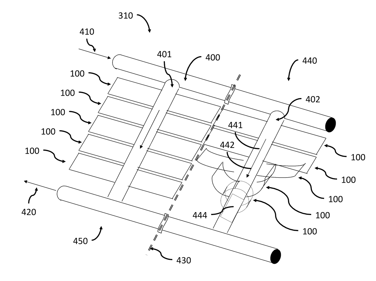
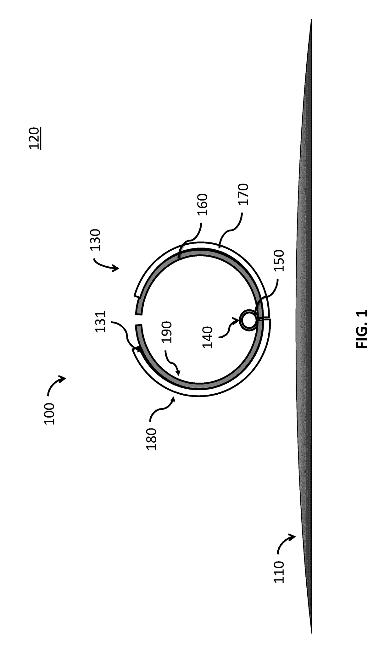
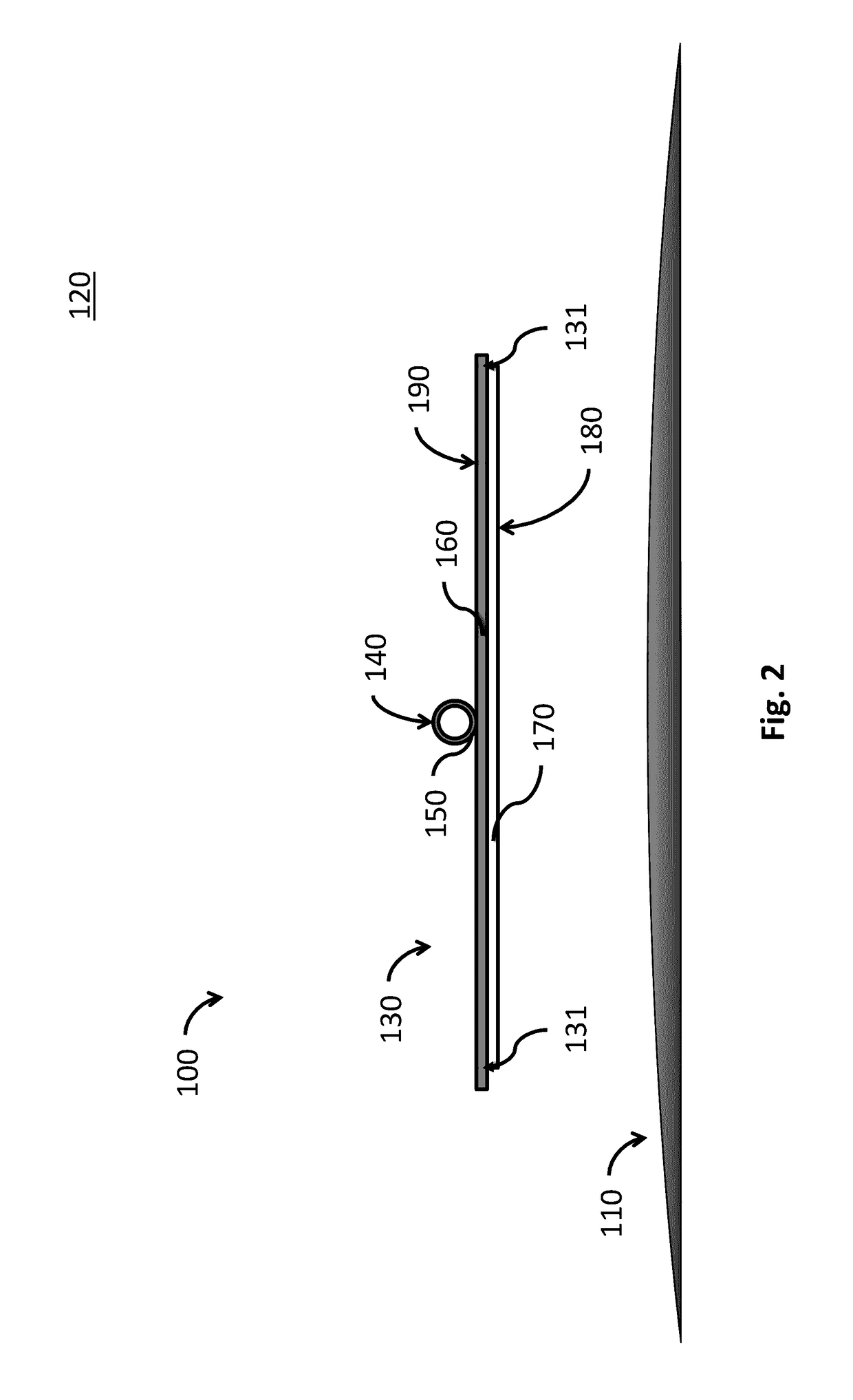
[0023]FIG. 1 and FIG. 2 show a diagrammatic cross sectional view illustrating a cold or low heat rejection state and a warm or high heat rejection state, respectively, of thermal energy radiator system 100 at least one of which comprises a key and enabling element of a heat rejection system 300 (see FIG. 3) according to a preferred embodiment of the present invention. A spacecraft, satellite or other extraterrestrial vehicle 110 (shown in part only and to rough scale) preferably includes an environment 310 for crew 320, heat generating hardware and systems 330, or both, and at least one thermal energy radiator system 100. Heat is preferably collected from heat sources within the vehicle 110 and transported to a heat rejection system 300 by means of a thermal control system 310.

[0024]Extraterrestrial environment 120 comprises a range of temperatures and other conditions that are uninhabitable by humans and inhospitable to electronics, avionics and hardware, and thus requires the use ...


PUM

PropertyMeasurementUnit
heat rejection capacityaaaaaaaaaa
thermal energyaaaaaaaaaa
temperatureaaaaaaaaaa

Abstract

A heat rejection system that employs temperature sensitive shape memory materials to control the heat rejection capacity of a vehicle to maintain a safe vehicle temperature. The technology provides for a wide range of heat rejection rates by varying the shape and thus effective properties of the heat rejection system in response to temperature. When employed as a radiator for crewed spacecraft thermal control this permits the use of higher freezing point, non-toxic thermal working fluids in single-loop thermal control systems for crewed vehicles in space and other extraterrestrial environments.

Description

CROSS REFERENCE TO RELATED APPLICATION[0001]The present application is related to and claims priority from prior provisional application Ser. No. 62 / 123,999, filed Dec. 4, 2014, entitled “A device for variable heat rejection through passive shape change in response to temperature”, the contents of which are incorporated herein by this reference and are not admitted to be prior art with respect to the present invention by the mention in the cross-reference section.STATEMENT REGARDING FEDERALLY SPONSORED RESEARCH OR DEVELOPMENT[0002]Some embodiments of this invention were developed with United States Government support under the National Aeronautics and Space Administration (NASA) announcement NNL12A3001N through award 12-12GCTC-0013. The Government may have certain rights in the invention.BACKGROUND[0003]This invention relates to providing a system for improved heat rejection. More particularly, this invention relates to providing a system for variable heat rejection in vehicles that...

Claims


Application Information

Patent Timeline
Patent Type & Authority Applications(United States)
IPC IPC(8): F28F5/00F28F3/02F28D15/00
CPCF28F5/00F28D15/00F28F3/02F28F2245/06F28F2255/04F28F2255/02F28D2021/0021B64G1/503F28F1/14F28F13/00F28F2215/14B64G1/50
Inventor COGNATA, THOMAS J.HARTI, DARRENDINSMORE, CRAIG E.SHETH, RUBIK
Owner COGNATA THOMAS JASPERO
Why Eureka
Try Eureka