
Device and method for polishing or abrading products

Inactive Publication Date: 2017-06-15
EUROSIDER S DI MILLI OTTAVIO & C
View PDF0 Cites 1 Cited by
  • Summary
  • Abstract
  • Description
  • Claims
  • Application Information

AI Technical Summary

Benefits of technology

This patent describes a polishing method that uses heat-conditioned air to protect the surface of products during polishing. The air is injected between the fibers of wool or other materials commonly used in polishing pads, keeping the surface cool even at high speeds. This reduces the risk of damage to the polished surface, particularly film of paint. Additionally, this method does not create holograms on the surface, resulting in a high-quality, scratch-free finish.

Problems solved by technology

However, known systems are not satisfactory since their use entails progressive and / or violent rise in temperature, which is dangerous for the surface being treated, on account of the operating friction between the polishing pad chosen and the surface of the product to be polished.
A further drawback is represented by the considerable interference that is caused by the relative humidity present in the operating environment and by the high temperatures of the environment, for example in summer periods or in given localities, in addition to the dust in suspension in the polishing environments.
In the case of painted products, the rise in temperature of the materials (plastic material, aluminium, ferrous materials, products made of glossy lacquered wood, etc.) inevitably leads, in fact, to serious problems of loss of elasticity of the underlying film of paint causing pattern formation, lesions and cracking, but also phenomena of halos and so-called holograms, i.e., marks left by traditional random-orbital polishers on the polished products.

Method used


Image

  • Device and method for polishing or abrading products
  • Device and method for polishing or abrading products
  • Device and method for polishing or abrading products

Examples


Embodiment Construction

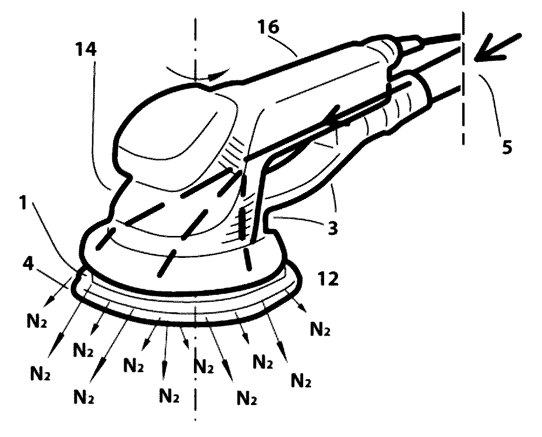
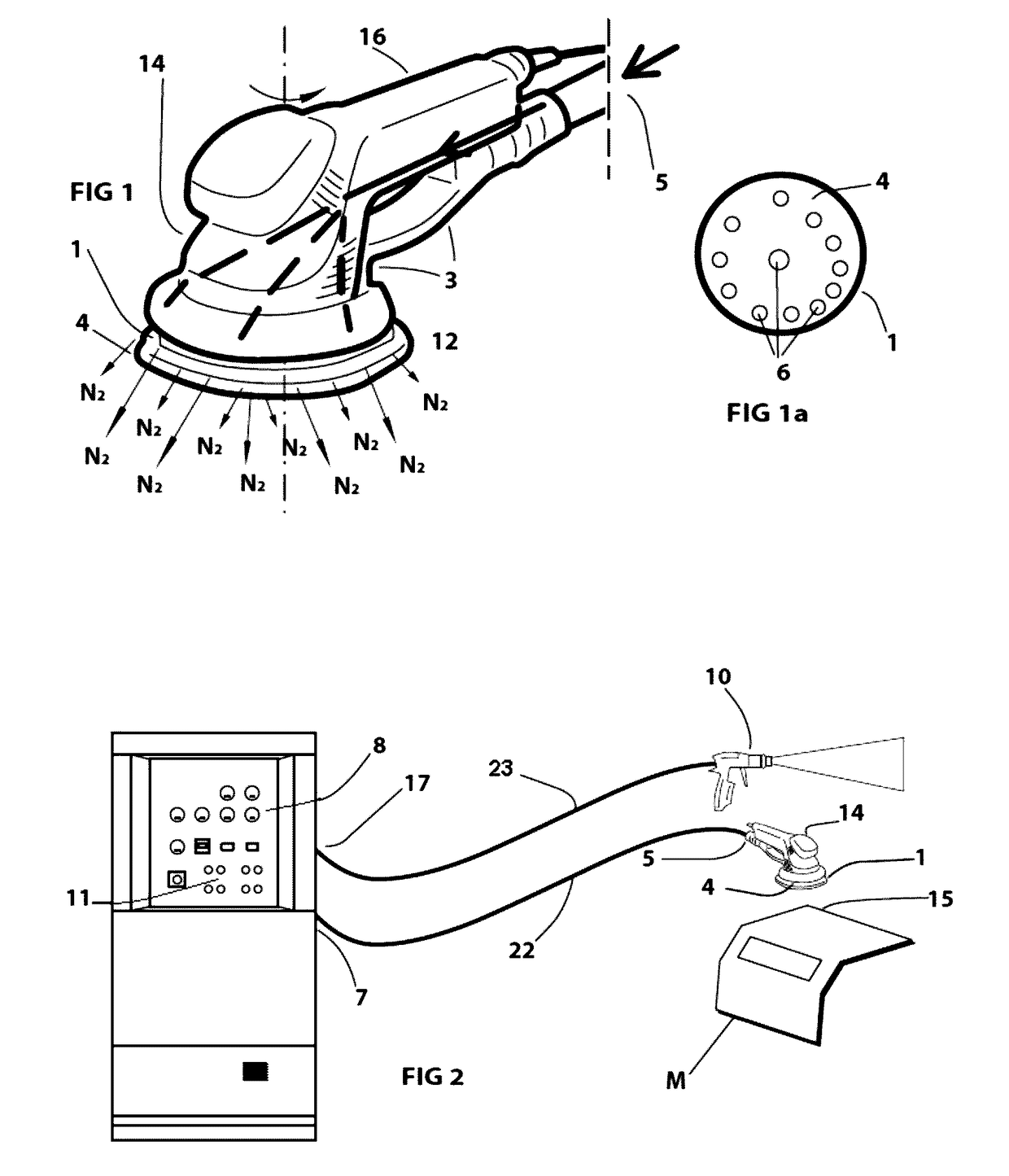
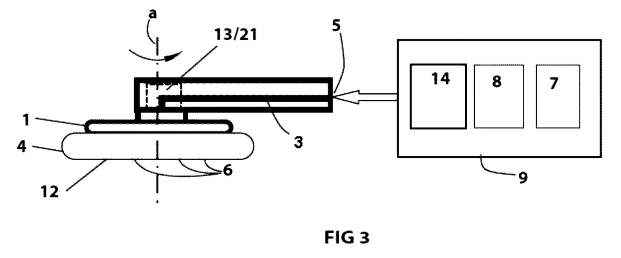
[0022]With reference to the attached drawings, there now follows a description of a device for polishing and / or sanding products M, in particular but in a non-limiting way, painted products.

[0023]The device comprises a disk 1 provided with an operating surface 4, which, in use, assumes a circular or orbital movement obtained with appropriate means 13, for example an electric or pneumatic motor, capable of impressing the polishing motion on the operating surface 4.

[0024]Preferably, removably applied on the surface 4 of the disk is a polishing pad 12 permeable to a flow of gas.

[0025]According to the invention, the device comprises a source 7 of a flow of treated air, for example cooled dry air, or nitrogen, or nitrogen-rich modified air, and one or more air ducts 3 extending from an inlet opening 5, which communicates with the source 7 by means of ducts 22, to one or more outlets 6 for the flow of treated air, located on the operating polishing surface 4, for example in areas correspo...


PUM


Abstract

A device for polishing or abrading products (M), includes: a polishing element (1) provided with an operating surface (4) designed to perform a polishing or sanding movement, preferably a circular or orbital movement;motor elements (13) operatively connected to the polishing element (1) for impressing on the operating surface (4) the polishing movement;one or more air ducts (3) extending from an inlet opening (5), which communicates with a source (7) of a flow of treated air, for example dried air, gaseous nitrogen, or modified air rich in nitrogen, to one or more outlets (6) of the flow distributed in an area corresponding to the operating surface (4); andelements (8) for regulating the temperature of the flow of treated air at a value comprised between −5° C. and +20° C.

Description

SECTOR OF THE INVENTION[0001]The invention relates to the sector of polishing and / or sanding of products, and in particular of polishing of metal substrates, for example made of steel or brass, or else of painted products.[0002]More in particular, the invention regards the sector of polishing of painted substrates using pads, whether with rotary or orbital motion, for example of the type used in vehicle-body repair or in the motor-vehicle industry in general or again in the industry of wood and plastic.STATE OF THE ART[0003]There have been known and marketed for some time polishing devices, rotary and random-orbital polishers actuated by electric motors or pneumatic turbines, which use a pad that is set in rotation by a tool and that is passed over the product possibly in combination with abrasive polishing pastes or creams.[0004]However, known systems are not satisfactory since their use entails progressive and / or violent rise in temperature, which is dangerous for the surface bein...

Claims


Application Information

Patent Timeline
IPC IPC(8): B24B55/02B24B23/04B24B23/02
CPCB24B55/02B24B23/04B24B23/026B24B23/02B24B37/015B24B53/095
Inventor MILLI, OTTAVIO
Owner EUROSIDER S DI MILLI OTTAVIO & C
Learn More