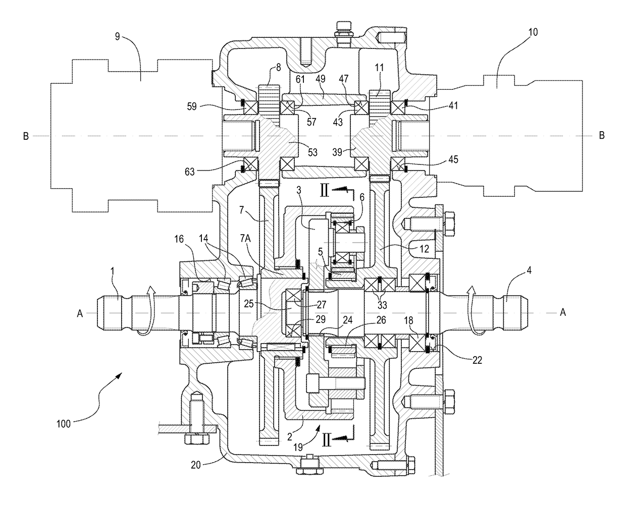
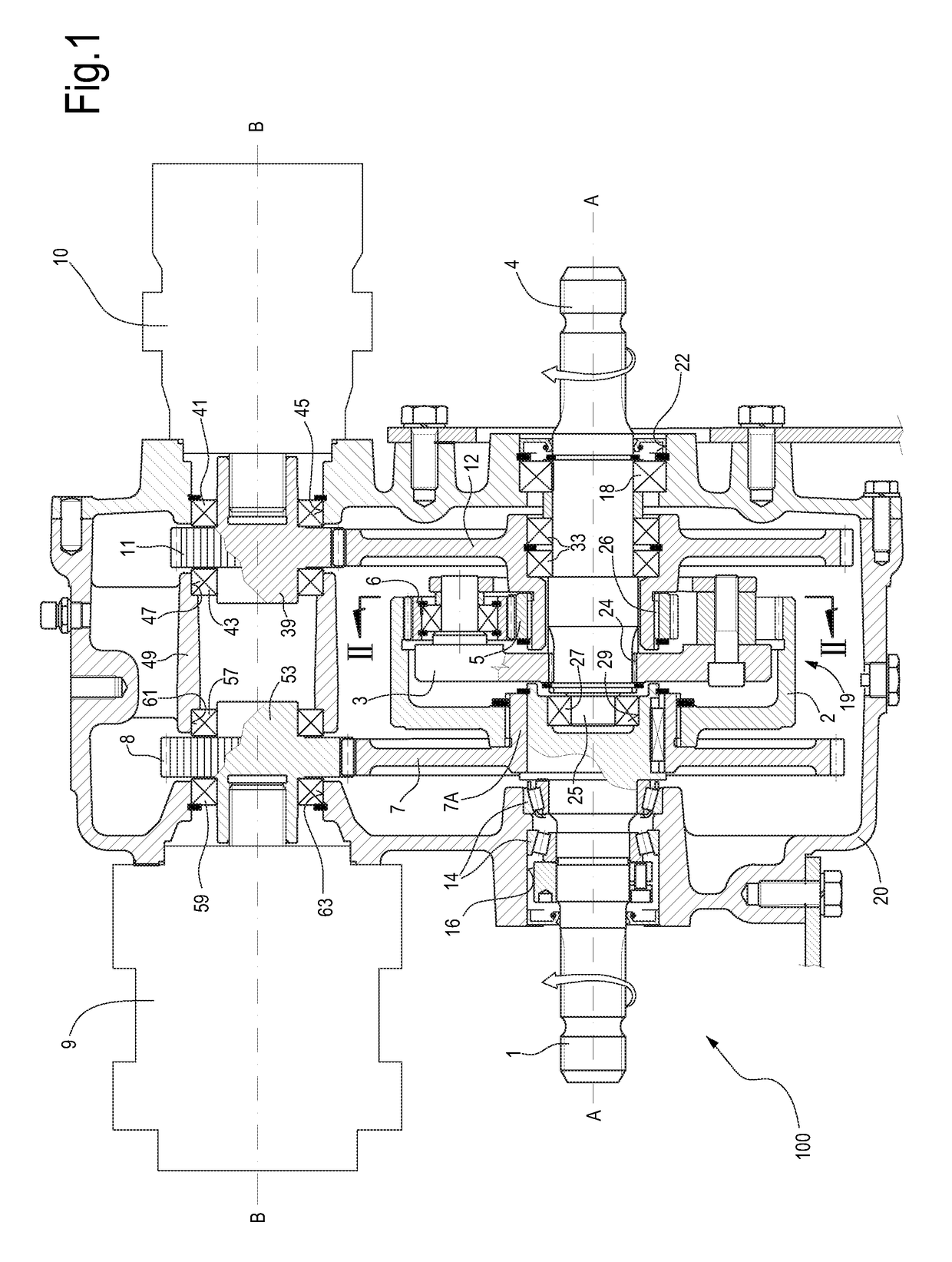
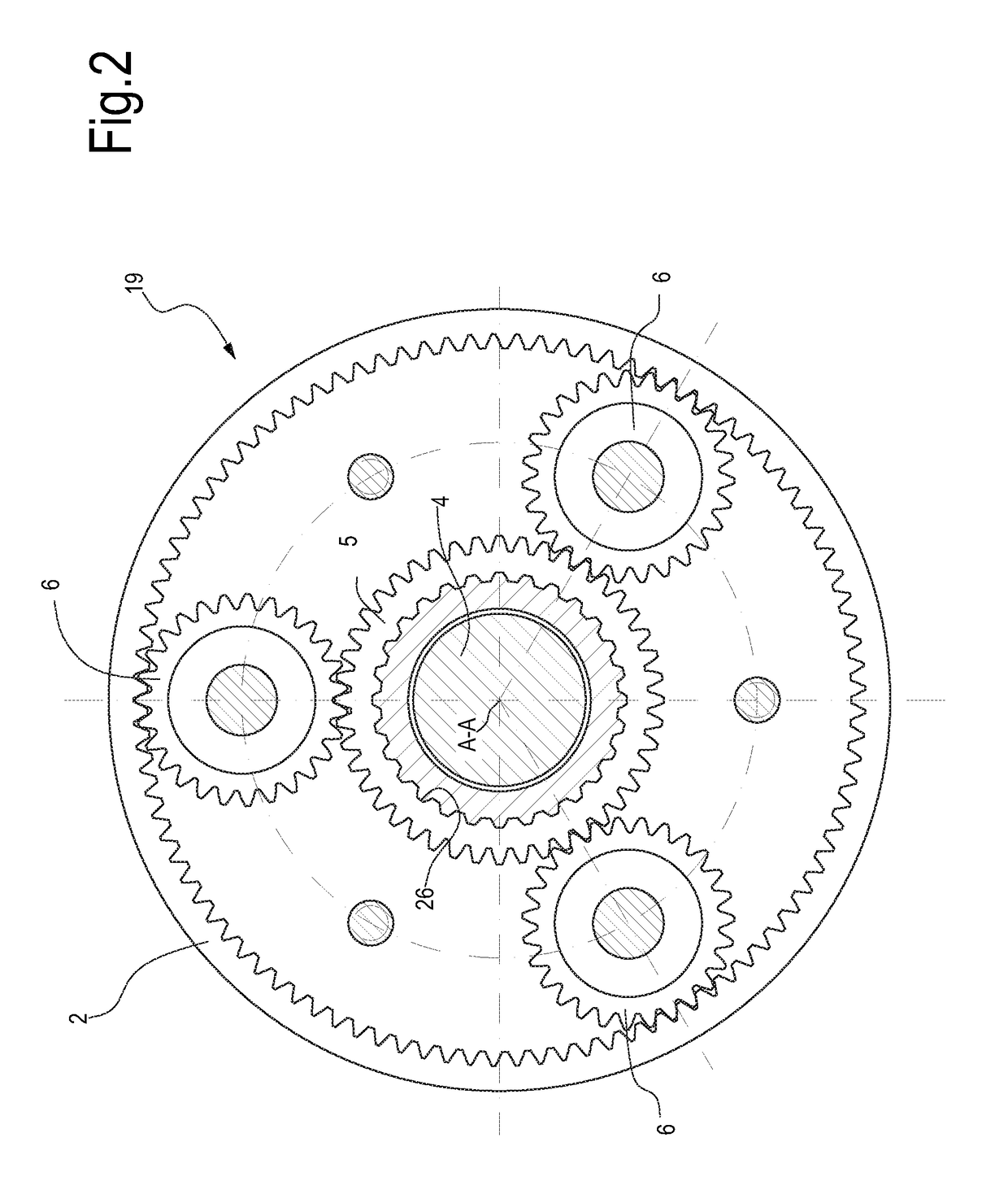
System comprising a mixer-wagon, for mixing and distributing fodder, and a mechanical power transmission unit for actuating the mixer-wagon

a technology of mechanical power transmission and mixer-wagon, which is applied in the direction of toothed gearings, animal feeding devices, gearing, etc., can solve the problems of slow mixing speed, inability to adjust the speed of the mechanical power transmission, and the auger to restart, so as to reduce the number of toothed wheels and improve the efficiency. , the effect of compact mechanical

Active Publication Date: 2017-06-15
BONDIOLI EDI
View PDF15 Cites 11 Cited by
  • Summary
  • Abstract
  • Description
  • Claims
  • Application Information

AI Technical Summary

Benefits of technology

[0026]In advantageous embodiments, in order to have a particularly compact mechanical power transmission unit, the second shaft, to which the planet-carrier is torsionally coupled, extends inside the sun gear, and the planet carrier is arranged between the sun gear and the first shaft. In this way, it is possible to obtain a mechanical power transmission unit with a reduced number of toothed wheels, and therefore high efficiency, with a reduction in mechanical losses and therefore a lower heat generation than the mechanical transmission units of the prior art.
[0027]The motion source may be pa

Problems solved by technology

In so-called mixer-wagons, or silage cutters, or total mixed ration wagons, particular problems occur in the mechanical power transmission with variable number of revolutions.
During the moving step, a slow mixing speed is required in order to avoid the material contained in the tank conglomerating, otherwise, the subsequent restart of the augers when the tank is full could be critical due to the high torque peaks generated in the mechanical transmission.
These mechanical gear boxes have some disadvantages in the various steps.
In particular, during chopping it is possible to adjust the work speed only by changing the rotation speed of the tractor endothermic engine, with consequent inefficiencies as regards the fuel consumption.
The compl

Method used


Image

  • System comprising a mixer-wagon, for mixing and distributing fodder, and a mechanical power transmission unit for actuating the mixer-wagon
  • System comprising a mixer-wagon, for mixing and distributing fodder, and a mechanical power transmission unit for actuating the mixer-wagon
  • System comprising a mixer-wagon, for mixing and distributing fodder, and a mechanical power transmission unit for actuating the mixer-wagon

Examples


Embodiment Construction

[0035]The following detailed description of the exemplary embodiments refers to the accompanying drawings. The same reference numbers in different drawings identify the same or similar elements. Additionally, the drawings are not necessarily drawn to scale. Also, the following detailed description does not limit the invention. Instead, the scope of the invention is defined by the appended claims.

[0036]Reference throughout the specification to “one embodiment” or “an embodiment” or “some embodiments” means that the particular feature, structure or characteristic described in connection with an embodiment is included in at least one embodiment of the subject matter disclosed. Thus, the appearance of the phrase “in one embodiment” or “in an embodiment” or “in some embodiments” in various places throughout the specification is not necessarily referring to the same embodiment(s). Further, the particular features, structures or characteristics may be combined in any suitable manner in one...


PUM


Abstract

A system is described comprising a mixer-wagon and a mechanical power transmission unit to actuate the rotating members of the mixer-wagon; the transmission unit comprises a box, a first shaft accessible from the outside of the box and a second shaft accessible from the outside of the box. The first shaft and the second shaft are coupled by means of an epicyclical gear train.

Description

TECHNICAL FIELD[0001]The present invention relates to improvements to systems for actuating mixer-wagons for mixing and distributing fodder. More particularly, the present invention relates to improvements to a mechanical power transmission unit to transmit motion from a drive shaft, connected to a power source, to driven shaft of the mixer-wagon.STATE OF THE ART[0002]In many mechanical applications, for instance in some agricultural machines, it is necessary to transmit motion between a drive shaft and a driven shaft, and in some cases the motion transmission ratio shall be variable. In so-called mixer-wagons, or silage cutters, or total mixed ration wagons, particular problems occur in the mechanical power transmission with variable number of revolutions. The mixer-wagons are used for preparing and distributing fodder for ruminant farm animals. The mixer-wagons can be self-propelled or towed. The towed mixer-wagon is coupled to a tractor, through which it is moved from the area wh...

Claims


Application Information

Patent Timeline
IPC IPC(8): F16H3/72A01K5/00
CPCA01K5/004F16H3/72F16H47/04F16H2037/088F16H37/0806
Inventor BONDIOLI, EDI
Owner BONDIOLI EDI
Why Eureka
Try Eureka