Silicon biporous wick for high heat flux heat spreaders

a heat spreader and heat flux technology, applied in the direction of electrical equipment, basic electric elements, lighting and heating equipment, etc., can solve the problems of cooling system not optimally dispersing heat from the device, degrading the performance of the device, etc., and achieve the effect of eliminating any contact resistan

Active Publication Date: 2017-06-15
CALIFORNIA INST OF TECH
View PDF3 Cites 3 Cited by
  • Summary
  • Abstract
  • Description
  • Claims
  • Application Information

AI Technical Summary

Benefits of technology

[0020]5. The TGP / heat spreader of any of the preceding embodiments, wherein the TGP comprises an air cooled heat sink as an extension of the top surface of the TGP. The air cooled heat sink entirely eliminates any contact resistance resulting from the use of an attached heat sink.

Problems solved by technology

Unless the heat is effectively extracted from the device, the device's performance will be degraded.
However, if the cooling system is not effectively coupled to the heat source in the device, the cooling system does not optimally dissipate the heat from the device.

Method used


Image

  • Silicon biporous wick for high heat flux heat spreaders
  • Silicon biporous wick for high heat flux heat spreaders
  • Silicon biporous wick for high heat flux heat spreaders

Examples


Embodiment Construction

[0035]In the following description of the preferred embodiment, reference is made to the accompanying drawings which form a part hereof, and in which is shown by way of illustration a specific embodiment in which the invention may be practiced. It is to be understood that other embodiments may be utilized and structural changes may be made without departing from the scope of the present invention.

[0036]Technical Description

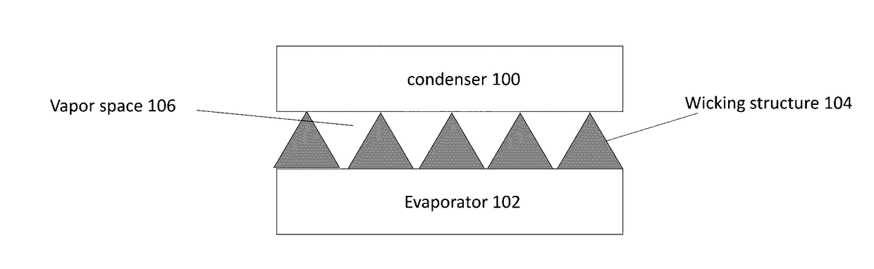
[0037]FIG. 1 illustrates a thermal ground plane (TGP) or heat spreader, comprising a condenser 100, an evaporator 102 (including wicking structure including biporous wick 104), and a vapor space 106.

[0038]In one or more embodiments, the wick at the evaporator side and the vapor space between the wick and the condenser side of the TGP are both optimized to accommodate / transport a heat flux of at least 1 kW / cm2. In this case, design of the vapor space is crucial due to the losses associated with restriction of the vapor escape from the evaporator. In one or more emb...


PUM

PropertyMeasurementUnit
diameteraaaaaaaaaa
pore sizesaaaaaaaaaa
diameteraaaaaaaaaa

Abstract

A wicking structure comprising a biporous wick formed with a semiconductor (e.g., silicon), wherein the biporous wick comprises first pores and second pores formed by the semiconductor and the first pores are larger than the second pores.

Description

CROSS REFERENCE TO RELATED APPLICATIONS[0001]This application claims the benefit under 35 U.S.C. Section 119(e) of co-pending and commonly-assigned U.S. Provisional Patent Application Ser. No. 62 / 266,188, filed on Dec. 11, 2015, by Eric T. Sunada, Karl Y. Yee, and Sean W. Reilly, entitled “ETCHED SILICON BIPOROUS WICK FOR HIGH HEAT FLUX HEAT SPREADERS”, (CIT-7381); which application is incorporated by reference herein.STATEMENT REGARDING FEDERALLY SPONSORED RESEARCH AND DEVELOPMENT[0002]The invention described herein was made in the performance of work under a NASA contract NNN12AA01C, and is subject to the provisions of Public Law 96-517 (35 USC 202) in which the Contractor has elected to retain title.BACKGROUND OF THE INVENTION[0003]1. Field of the Invention[0004]This invention relates to a heat spreader or thermal ground plane (TGP) comprising a biporous wick.[0005]2. Description of the Related Art[0006](Note: This application references a number of different publications as indi...

Claims


Application Information

Patent Timeline
Patent Type & Authority Applications(United States)
IPC IPC(8): F28D15/04F28F21/04F28F13/00
CPCF28D15/046F28F21/04F28F13/003H01L23/427
Inventor SUNADA, ERIC T.YEE, KARL Y.REILLY, SEAN W.
Owner CALIFORNIA INST OF TECH
Why Eureka
Try Eureka