Motor vehicle battery disconnect switch circuits

a technology of battery disconnect and switch circuit, which is applied in the direction of safety/protection circuit, engine starter, machine/engine, etc., can solve the problems of non-trivial voltage drop, attendant heating, and the possibility of operation of cranking motor, so as to avoid inadvertent battery drain

Active Publication Date: 2005-01-06
INT TRUCK INTPROP LLC
View PDF4 Cites 2 Cited by
  • Summary
  • Abstract
  • Description
  • Claims
  • Application Information

AI Technical Summary

Benefits of technology

[0006] The present invention relates to disconnect switch circuits that are believed to offer better solutions for avoiding inadvertent battery draining when a vehicle is parked for an extended period of time. Rather than placing a disconnect switch in circuit between a battery bank and a distribution point for the entire electrical system load, the invention places the disconnect switch between the battery bank and a distribution point for the entire system load except the engine cranking motor. This allows the circuit between the battery bank and the contacts of a cranking motor solenoid that is energized to run the cranking motor to be switch-free. The cranking motor solenoid is often integrated with the cranking motor itself, rather

Problems solved by technology

And although some might consider that resistance small, it is significant when the large amperage of the cranking current is considered.
Large current flowing through even a small resistance creates a non-trivial voltage drop and attendant heating.
First, operation of t

Method used


Image

  • Motor vehicle battery disconnect switch circuits
  • Motor vehicle battery disconnect switch circuits
  • Motor vehicle battery disconnect switch circuits

Examples


Embodiment Construction

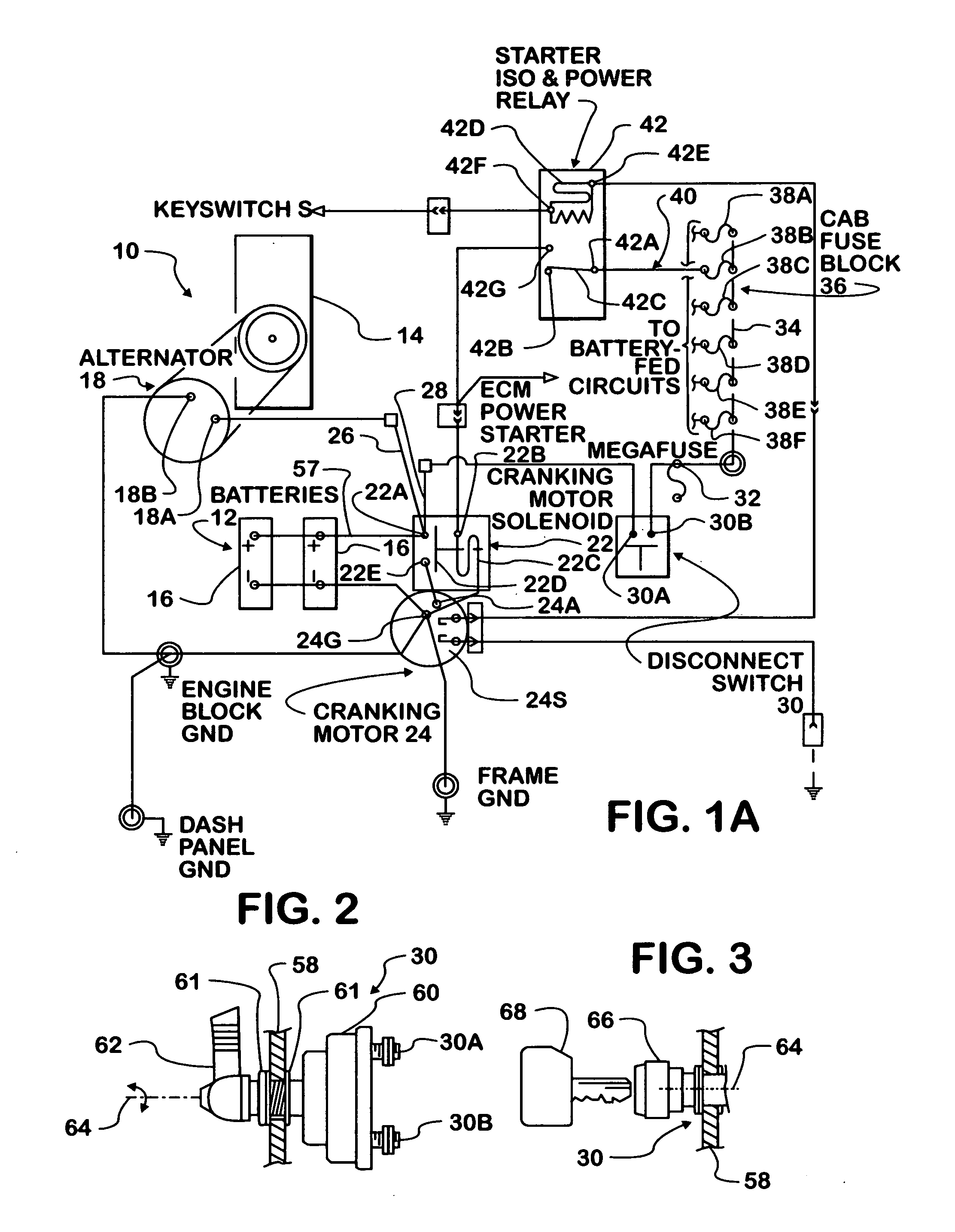
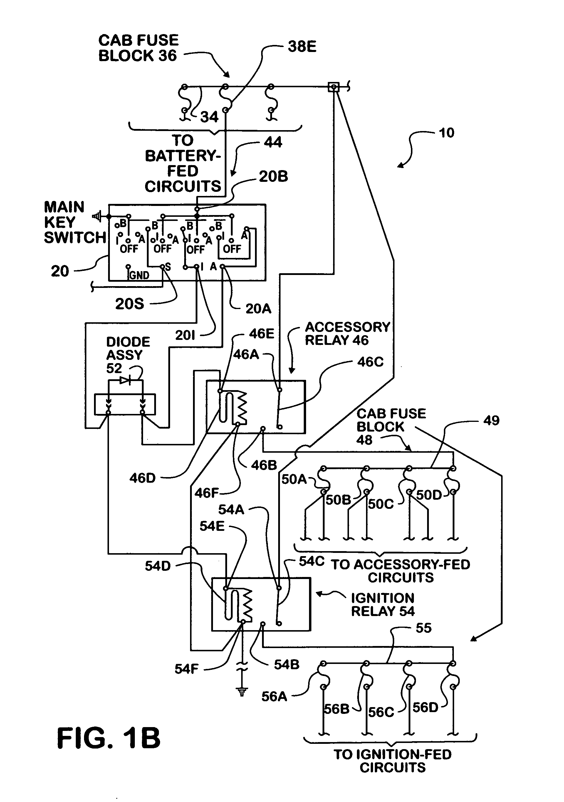
[0023]FIGS. 1A and 1B collectively show a portion of a motor vehicle electrical system 10 that incorporates a battery disconnect switch circuit according to principles of the present invention. In this example, the vehicle is a truck that has a chassis and is powered by a diesel engine. The truck may be a tractor that has a fifth wheel for haul a trailer. The truck cab, or body, is mounted on the chassis rearward of an engine compartment that houses the engine and a battery bank. The engine has an electric cranking motor and an associated cranking motor solenoid that is energized to operate the cranking motor at engine starting.

[0024] Electrical system 10 comprises a battery bank 12 containing one or more individual D.C. storage batteries 16. In a heavy truck powered by a diesel engine, such as engine 14, battery bank 12 contains multiple batteries 16 ganged together. When engine 14 is running, batteries 16 are kept charged by an engine-driven alternator 18 having positive and nega...


PUM


Abstract

A disconnect switch (30, 30SA) is placed in circuit between a battery bank (12) and a distribution point (30B) for the entire electrical system load except the engine cranking motor (24). This allows the circuit between the battery bank and a cranking motor solenoid (22) that operates the cranking motor to be switch-free. A switch-free circuit allows a continuous cable to connect the battery bank to the cranking motor solenoid, significantly reducing the electrical resistance between the battery bank and the cranking motor solenoid.

Description

FIELD OF THE INVENTION [0001] This invention relates generally to electrical systems of motor vehicles. More particularly, the invention relates to battery disconnect circuits for preventing battery drain when the engine does not run for extended periods of time. BACKGROUND OF THE INVENTION [0002] Certain motor vehicles, heavy trucks that are powered by diesel engines for example, may be parked for extended periods of time. If its engine is allowed to keep running after a vehicle has been parked, the alternator should be effective to keep the battery bank charged. If the engine is shut down, either intentionally by the driver, or automatically by a device such as an idle shutdown timer, while the circuits for electric devices remain on, the battery bank will begin to drain. For example, an ignition switch will typically remain on after an idle shutdown timer has timed out, and certain circuits that are left on may continue to draw current. [0003] Because the battery bank must be abl...

Claims


Application Information

Patent Timeline
IPC IPC(8): B60R16/02B60R16/03H02J7/00
CPCB60R16/03F02N11/0862H02J7/0031H02J2310/46
Inventor BENDER, BURNELL L.
Owner INT TRUCK INTPROP LLC
Why Eureka
Try Eureka