Flux shield having split structures and generator including the same

a split structure and flux shield technology, applied in the direction of structural associations, electrical appliances, dynamo-electric machines, etc., can solve the problems of further increase in production costs, increased cost of materials, increased production costs, etc., and achieves the effect of reducing production and assembly costs, easy assembly and management, and convenient fabricated

Active Publication Date: 2017-06-15
DOOSAN HEAVY IND & CONSTR CO LTD
View PDF1 Cites 0 Cited by
  • Summary
  • Abstract
  • Description
  • Claims
  • Application Information

AI Technical Summary

Benefits of technology

[0017]The flux shield according to an embodiment of the present disclosure includes the two or more split structures spaced apart from each other at specific intervals. Accordingly, the flux shield which can be easily fabricated, can be easily assembled and managed, and can reduce the cost of production and assembly and management costs and a generator including the same can be provided.
[0018]Furthermore, the flux shield according to an embodiment of the present disclosure can be fabricated to have split structures of various forms, such as a radial point symmetry structure, a left and right symmetry structure or a top and bottom symmetry structure. Accordingly, the flux shield can be easily fabricated compared to a flux shield according to a conventional technology, and thus the cost of production can be significantly reduced.
[0019]Furthermore, the flux shield according to an embodiment of the present disclosure has the structure split into two or more pieces. Accordingly, a mounting and assembly task can be performed more easily compared to a conventional technology in mounting the flux shields on both ends of a generator.
[0020]Furthermore, the flux shield according to an embodiment of the present disclosure can be easily fabricated compared to a flux shield according to a conventional technology because it includes one or more step structures corresponding to a shape of both ends of a generator and has the split structures formed along the curved portions of the step structures. Accordingly, the cost of production can be significantly reduced, and a mounting and assembly task can be performed more easily compared to a conventional technology in mounting the flux shields on both ends of a generator.
[0021]Furthermore, the flux shield according to an embodiment of the present disclosure can be easily applied to generators of various specifications in addition to a generator of specific specifications because the interval between the split structures and the number of split pieces can be properly changed depending on the specifications of a generator and / or a designer's intention.
[0022]Furthermore, the generator according to an embodiment of the present disclosure can significantly reduce the cost of production and production costs because it includes the flux shields according to an embodiment of the present disclosure.

Problems solved by technology

In this case, since the magnetic flux shield plates have to be fabricated in an integrated manner, the cost of production of the magnetic flux shield plate and the cost of materials thereof are increased.
Furthermore, if both ends of the generator have a complicated structure, the cost of production is further increased.

Method used


Image

  • Flux shield having split structures and generator including the same
  • Flux shield having split structures and generator including the same
  • Flux shield having split structures and generator including the same

Examples


Embodiment Construction

[0034]Hereinafter, embodiments of the present disclosure are described in detail with reference to the accompanying drawings. Prior to the description, terms or words used in this specification and the claims should not be construed as being common or having those found in dictionaries, but should be construed having meanings and concepts which comply with the technical spirit of the present disclosure.

[0035]In the entire specification, when it is described that one member is placed “on or over” the other member, it means that one member may adjoin the other member and a third member may be interposed between the two members. In the entire specification, unless explicitly described to the contrary, the word “include, have, or comprise” will be understood to imply the inclusion of stated elements but not the exclusion of any other elements.

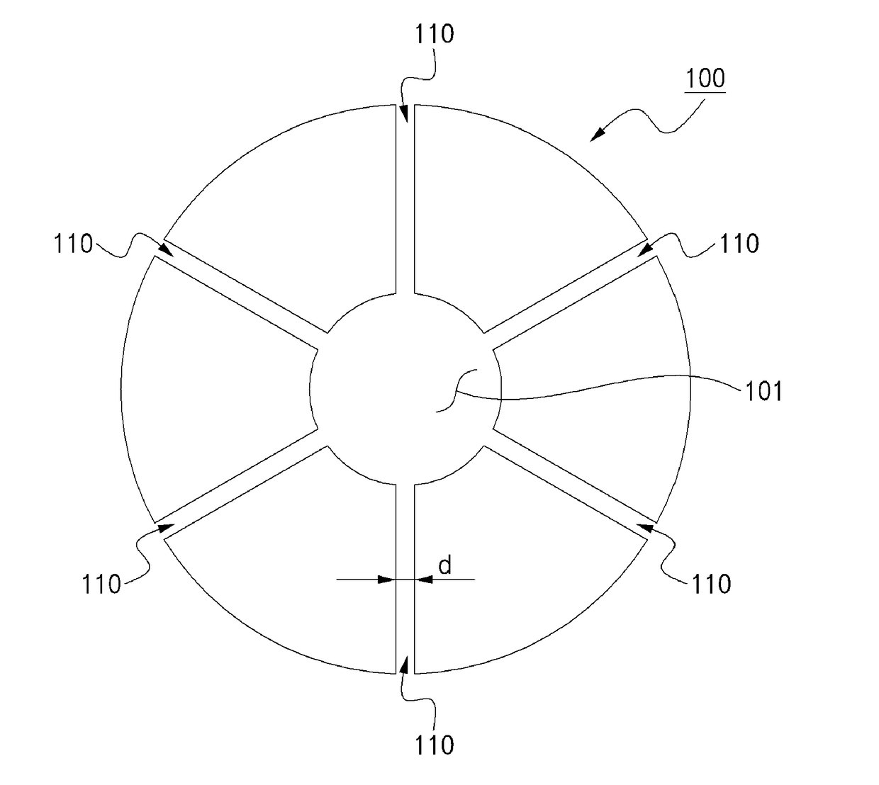
[0036]FIG. 5 is a plan schematic diagram showing a flux shield according to an embodiment of the present disclosure.

[0037]As shown in FIG. 5, the ...


PUM


Abstract

Disclosed herein are a flux shield and a generator including the same and, more particularly, a flux shield including split structures and a generator including the same.

Description

CROSS REFERENCE TO RELATED APPLICATION[0001]The present application claims the benefit of Korean Patent Application No. 10-2015-0179321 filed in the Korean Intellectual Property Office on Dec. 15, 2015, the entire contents of which are incorporated herein by reference.BACKGROUND[0002]The present disclosure relates to a flux shield and a generator including the same and, more particularly, to a flux shield including split structures and a generator including the same.[0003]FIG. 1 is a diagram showing a generator having flux shields for shielding a magnetic flux mounted thereon on both sides thereof, and FIG. 2 is a diagram showing one end portion of the generator from which a rotary rotor has been removed. Furthermore, FIG. 3 is a plan schematic diagram showing the flux shield of FIG. 2, and FIG. 4 is a diagram showing the state in which a magnetic flux is introduced form the outside to the inside of the generator.[0004]Referring to FIGS. 1 to 4, similar to a large amount of a magnet...

Claims


Application Information

Patent Timeline
Patent Type & Authority Applications(United States)
IPC IPC(8): H02K11/22
CPCH02K11/022H02K3/42H02K11/0141
Inventor SONG, DAEIL
Owner DOOSAN HEAVY IND & CONSTR CO LTD
Why Eureka
Try Eureka