Needle with piezoelectric polymer sensors

a piezoelectric polymer and needle technology, applied in applications, ultrasonic/sonic/infrasonic image/data processing, ultrasonic/sonic/infrasonic diagnostics, etc., can solve the problems of limited improvement, poor needle visibility, limited improvement,

Active Publication Date: 2017-06-22
KONINKLJIJKE PHILIPS NV
View PDF2 Cites 16 Cited by
  • Summary
  • Abstract
  • Description
  • Claims
  • Application Information

AI Technical Summary

Problems solved by technology

In ultrasound imaging, the visibility of the needle is often very poor due to the specular nature of the needle surface that reflects beams away from the imaging probe.
To alleviate this problem some needle manufacturers have produced needles with special echogenic coatings, but the visualization improvement is limited.
Ultrasound imaging syst

Method used


Image

  • Needle with piezoelectric polymer sensors
  • Needle with piezoelectric polymer sensors
  • Needle with piezoelectric polymer sensors

Examples


Embodiment Construction

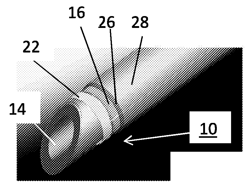
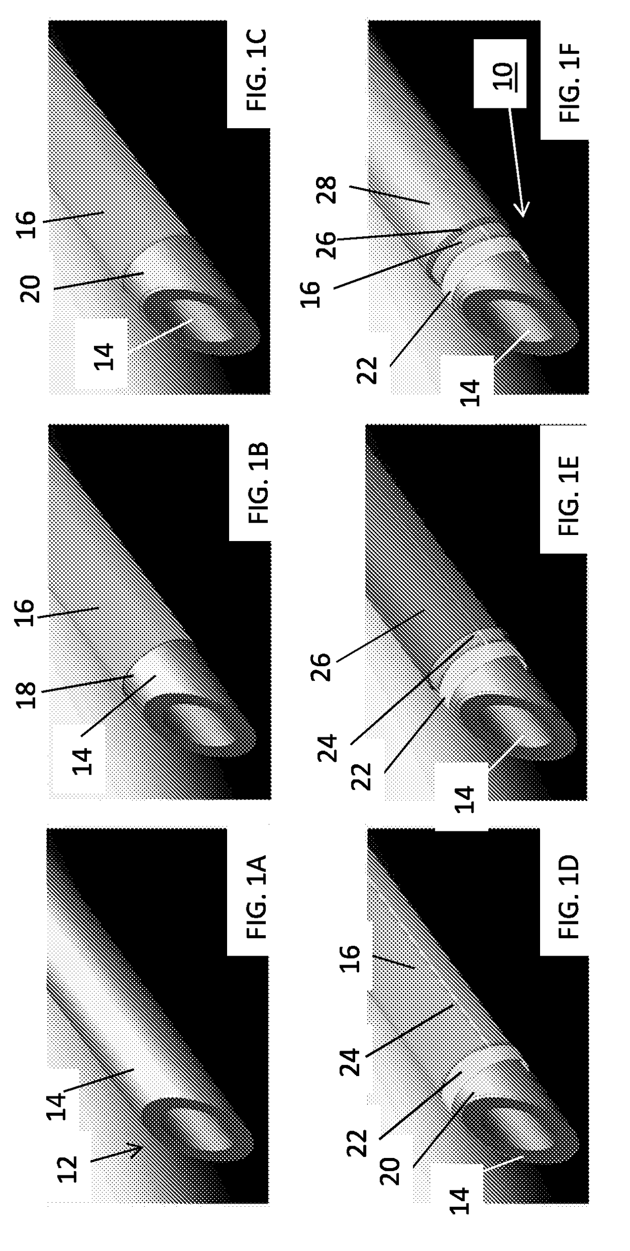
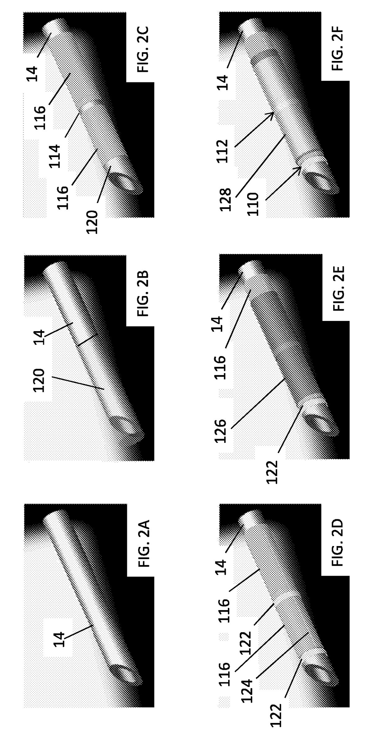
[0044]In accordance with the present principles, systems, devices and methods are provided for tracking a needle (or other device) under ultrasound guidance by attaching small ultrasound receivers onto the device. The present principles provide a needle, device or system that includes one or more low profile sensors at very low per device cost and permits scaling for mass production to maintain low cost.

[0045]The ultrasound sensors may be formed on the needle or other device and may be fabricated using a piezoelectric polymer, e.g., polyvinylidene fluoride (PVDF) or polyvinylidene fluoride trifluoroethylene (P(VDF-TrFE)). P(VDF-TrFE), which can be dissolved in acetone and applied to the needle through an evaporative process. The sensors are high impedance and can be modeled as a voltage source in series with a small capacitor (e.g., 2.2 pF). Such a sensor is very sensitive to capacitive loading of the electrical interconnect, and special capacitance cancelling electronics (similar t...


PUM


Abstract

A medical device includes a conductive body (14) including a surface and a sensor (10) conformally formed on the surface and including a piezoelectric polymer formed about a portion of the surface and following a contour of the surface. The piezoelectric polymer is configured to generate or receive ultrasonic energy. Electrical connections (24) conform to the surface and are connected to an electrode in contact with the piezoelectric polymer. The electrical connections provide connections to the piezo electric polymer and are electrically isolated from the conductive body over a portion of the surface.

Description

RELATED APPLICATION INFORMATION[0001]This application claims priority to U.S. provisional application Ser. No. 61 / 978,193, filed on Apr. 10, 2014, incorporated herein by reference in its entirety.BACKGROUND[0002]Technical Field[0003]This disclosure relates to medical instruments and more particularly to a system and method to track a tip of a needle or other devices under ultrasound guidance using ultrasound receivers formed on the needle.[0004]Description of the Related Art[0005]In ultrasound imaging, the visibility of the needle is often very poor due to the specular nature of the needle surface that reflects beams away from the imaging probe. To alleviate this problem some needle manufacturers have produced needles with special echogenic coatings, but the visualization improvement is limited. Ultrasound imaging system manufacturers have developed algorithms that use multiple imaging beams from varied angles, but improvement is limited and such a strategy is primarily suited only ...

Claims


Application Information

Patent Timeline
IPC IPC(8): A61B17/34A61B8/00A61B90/00A61B8/08
CPCA61B17/3403A61B17/3417A61B8/0841A61B8/4494A61B90/39A61B2090/3929A61B2018/00529A61B2018/1425A61B2018/00345A61B2034/2063A61B2090/3925A61B2017/3413A61B2018/0088
Inventor ERKAMP, RAMON QUIDOJAIN, AMEET KUMARVIGNON, FRANCOIS GUY GERARD MARIE
Owner KONINKLJIJKE PHILIPS NV
Why Eureka
Try Eureka