
Optical sensor for detecting a chemical species

a chemical species and optical sensor technology, applied in the field of optical sensors, can solve the problems of limited response time and/or the strength of colour/fluorescent response of prior art sensors, degrade very fast, and use of gas detection, etc., to achieve good compromise between amount of dye present and response time, the effect of improving the response time of a hierarchical optical sensing layer

Active Publication Date: 2017-06-22
CSEM CENT SUISSE DELECTRONIQUE & DE MICROTECHNIQUE SA RECH & DEV
View PDF2 Cites 6 Cited by
  • Summary
  • Abstract
  • Description
  • Claims
  • Application Information

AI Technical Summary

Benefits of technology

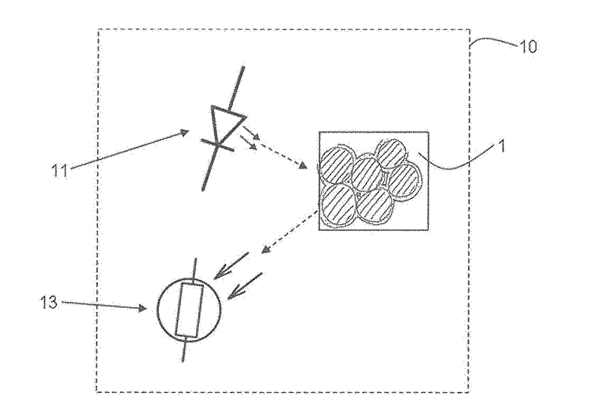
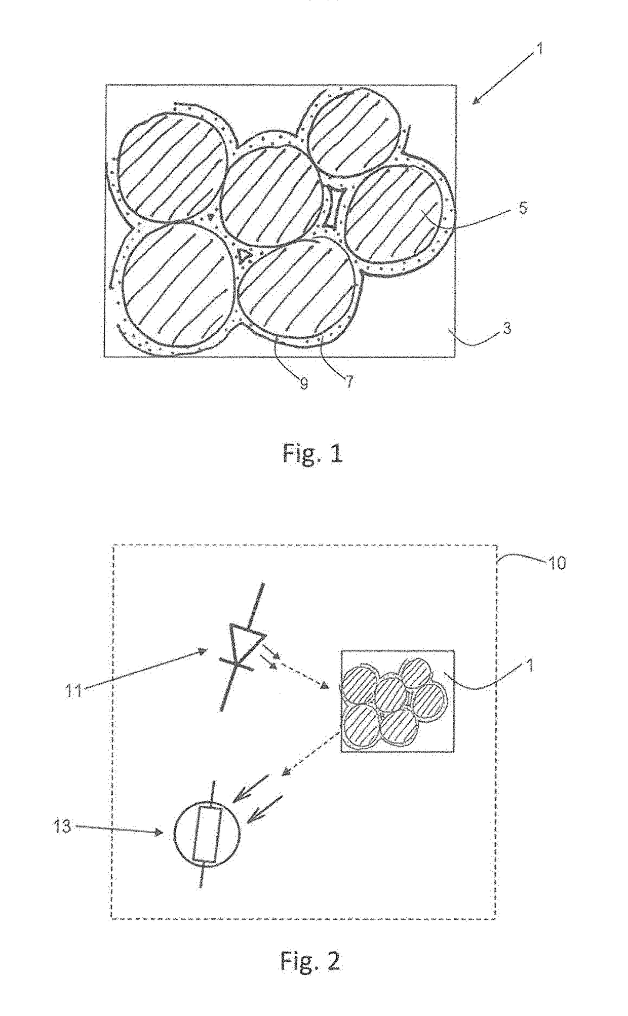
This patent describes an optical sensor that can detect chemical species in both gases and liquids, while preventing the dyes embedded in the sensor from leaching and photodegradation. The sensor has a hierarchical structure that improves its response time and stability in different aqueous solutions. The chemical species that can be detected include oxygen, carbon dioxide, and H+ or OH− ions, with dye molecules like bromophenol blue, alizarin, methyl red, and fluorescein being examples. The sensor has a microporous matrix that forms a layer ranging from 1-50 μm in thickness, allowing for a good compromise between the amount of dye present and its response time. The microporous matrix is also formed as a layer less than 1000 nm in thickness to prevent pore blocking. The sensor may be incorporated into a sensor system that includes a light source and a detector.

Problems solved by technology

However, these prior art sensors are restricted in their response time and / or the strength of their colour / fluorescent response due to limitations on the amount of dye which can be exposed to the chemical species of interest due to limited porosity of the substrates, and the need to keep the layers thin (typically 1 μm maximum) to ensure a reasonable response time and optical readout.
However, they can only be used for gas detection, unless a specific approach is used to prevent the sensitive compounds from leaching, such as the covalent bonding reported in U.S. Pat. No. 8,313,710.
Additionally, since the sensitive compounds are not entrapped in a tight environment in meso- and macroporous matrices, they degrade very fast, generating signal and sensitivity drift of the sensor.

Method used


Image

  • Optical sensor for detecting a chemical species
  • Optical sensor for detecting a chemical species
  • Optical sensor for detecting a chemical species

Examples


Embodiment Construction

[0046]FIG. 1 shows schematically a close-up view of the structure of an optical sensing layer 1 according to the invention. Sensing layer 1 comprises a substrate 3, which may be glass, plastic, ceramic, metal or any other convenient material, upon which is deposited a mesoporous matrix 5. A mesoporous material is defined as a material with pore diameter between 2 and 50 nm between individual, substantially non-porous particles of material. A typical mesoporous matrix 5 for this application is formed by metal oxide layers obtained by deposition of nanoparticles from solution, and is deposited on the substrate 3, which is typically flat although this does not have to be the case. The thickness of these layers is typically comprised between about 1 and about 50 μm, and the size and density of the mesoporous particles are chosen to preferably achieve a pore size in the range of 10-50 nm. The mesoporous matrix 5 thus provides a vastly-increased surface area compared to a flat surface, an...


PUM

PropertyMeasurementUnit
pore diametersaaaaaaaaaa

Abstract

Disclosed is an optical sensor (1) for detecting a chemical species, including:a substrate (3);a mesoporous matrix (5) disposed on the substrate;a microporous matrix (7) disposed within the mesoporous matrix, the microporous matrix (7) including an indicator dye (9) dispersed therein, the indicator dye (9) exhibiting changes in its optical properties in response to the presence of the chemical species.

Description

TECHNICAL FIELD[0001]The present invention relates to the field of optical sensors for detecting the presence of chemical substances, such as O2 and CO2, and also oxonium (H3O+) and / or hydroxide ions (OH−).STATE OF THE ART[0002]Luminescent gas sensors for detection of oxygen or carbon dioxide have been introduced in the market during the last decade. The most successful products so far are oxygen sensors that have been commercialized by several companies. Compared to electrochemical sensors they are more stable and are available in cheap—and accurate—devices. Many suppliers of electrochemical oxygen sensors, such as Mettler-Toledo, Hamilton, Hach Lange, and YSI, are now providing an optical version. A few companies are also providing patches that can be inserted into bottles or packages in order to optically measure the amount of oxygen from outside of the container, through its transparent wall. Companies which commercialise such products are Ocean Optics, Polestar, Pyro-Science, O...

Claims


Application Information

Patent Timeline
Patent Type & Authority Applications(United States)
IPC IPC(8): G01N21/64
CPCG01N21/645G01N2021/6439G01N21/6428B82Y30/00G01N31/221G01N31/223G01N21/6408G01N21/77G01N21/78G01N21/783G01N21/80G01N2021/6432G01N2021/6434G01N2021/7726G01N2021/7786G01N31/225G01N31/22G01N33/004
Inventor SCOLAN, EMMANUELWENGER, BERNARDPUGIN, RAPHAEL
Owner CSEM CENT SUISSE DELECTRONIQUE & DE MICROTECHNIQUE SA RECH & DEV
Learn More