Mux/demux comprising capillary filter block and methods of producing the same

a filter block and capillary filter technology, applied in the field of optical multiplexers/demultiplexers, to achieve the effect of increasing the capacity of optical communication systems, limiting the space in data centers, and rapid growth of data traffi

Active Publication Date: 2017-06-29
ALLIAN FIBER OPTIC PROD INC
View PDF11 Cites 7 Cited by
  • Summary
  • Abstract
  • Description
  • Claims
  • Application Information

AI Technical Summary

Benefits of technology

[0007]The present inventors have recognized that, because of limited space in data centers and the rapid growth of data traffic, there is an increasing need for capacity in optical communication systems. Increasing port density requires assemblies with ever smaller form factors. Integrating multiple components onto a single substrate is one of the key challenges facing miniaturization. Carefully locating and interrelating the components in a multiplexer / demultiplexer assembly can reduce the space required for the assembly and thus increase the number of assemblies and data rate of a given PON.
[0013]In accordance with yet another embodiment described herein, a method of producing a multiplexer / demultiplexer is provided. An optical and mechanical interface between a bonding face of a signal-routing block and a bonding face of a capillary filter block is formed using an index-matching adhesive. The layer thickness of the index-matching adhesive is sufficient to accommodate extra-planar surface irregularities in the bonding face of the signal routing block and extra-planar variations along the proximal ends of the component filter blocks of the capillary filter block. The index-matching adhesive is cured such that the signal-routing block and the capillary filter block are in fixed alignment.

Problems solved by technology

Integrating multiple components onto a single substrate is one of the key challenges facing miniaturization.

Method used


Image

  • Mux/demux comprising capillary filter block and methods of producing the same
  • Mux/demux comprising capillary filter block and methods of producing the same
  • Mux/demux comprising capillary filter block and methods of producing the same

Examples


Embodiment Construction

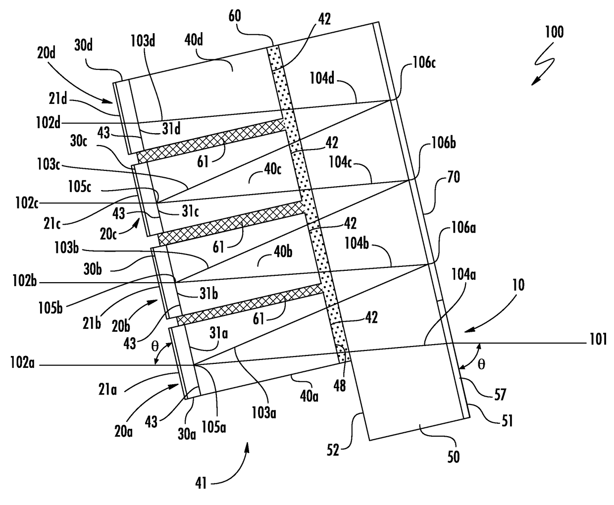
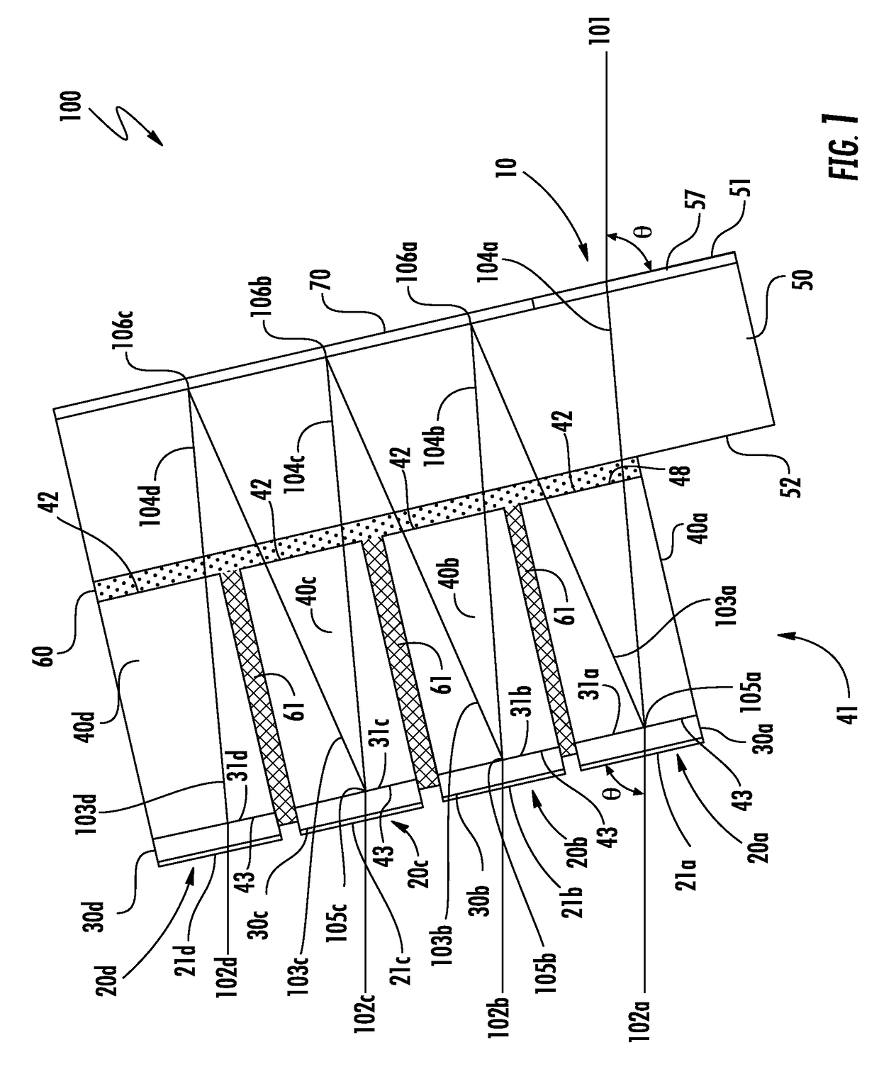
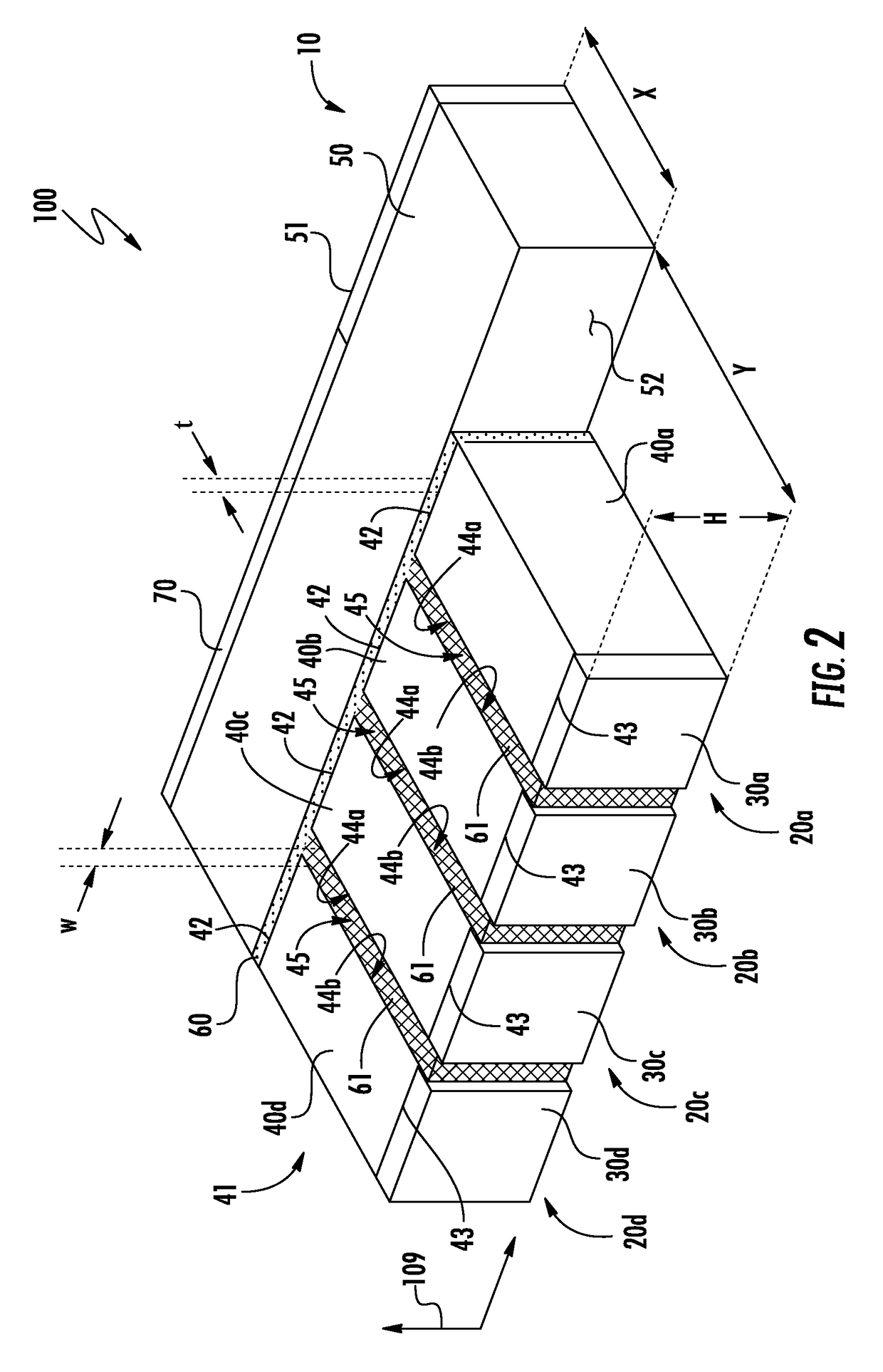
[0024]As illustrated in FIGS. 1 and 2, in certain embodiments, a multiplexer / demultiplexer 100 comprises a common port 10, a plurality of input / output ports 20a-20d, a capillary filter block 41 a signal-routing block 50, and an index-matching adhesive 60 between the capillary filter block 41 and the signal-routing block 50. The capillary filter block 41 comprises a plurality of component filter blocks 40a-40d secured together with a capillary adhesive 61 and each of the component filter blocks 40a-40d of the capillary filter block 41 comprises a proximal end 42, a distal end 43, and a pair of capillary side walls 44a, 44b (see FIG. 2) extending from the proximal end 42 of the component filter block 40a-40d to the distal end 43 of the component filter block 40a-40d. Each of the component filter blocks 40a-40d of the capillary filter block 41 further comprises a thin-film filter 30a-30d disposed at the distal end 43 of the component filter block 40a-40d.

[0025]Referring specifically t...


PUM


Abstract

A multiplexer / demultiplexer is provided comprising a capillary filter block, a capillary adhesive, a signal-routing block, and an index-matching adhesive. The capillary adhesive resides in the capillary interstices of the capillary filter block and the index-matching adhesive forms an optical and mechanical interface between the signal-routing block and the capillary filter block. The layer thickness of the index-matching adhesive accommodates for extra-planar surface irregularities in the bonding face of the signal routing block and extra-planar variations along the proximal ends of the component filter blocks of the capillary filter block. The capillary filter block can be formed from a plurality of component filter blocks by dicing multiple component filter blocks from a filter block substrate, placing the component filter blocks adjacent to one another, and using capillary force to draw adhesive between adjacent sidewalls of component filter blocks

Description

CROSS-REFERENCE TO RELATED APPLICATIONS[0001]This application claims the benefit of U.S. Provisional Application Ser. No. 62 / 387,574, filed Dec. 28, 2016.BACKGROUND[0002]Field[0003]The present disclosure relates to optical multiplexers / demultiplexers.[0004]Technical Background[0005]Wavelength division multiplexing (WDM) is the name given to the technology employed to add (or multiplex) a number of distinct wavelengths of light onto a single optical fiber, increasing information capacity and enabling bi-directional flow of signals. It is contemplated that, by combining multiple channels of light into a single channel, current multiplexer / demultiplexer assemblies can reach data transmission speeds up to 160 TB / s, or more.[0006]Multiplexer / demultiplexer assemblies can be used as components in passive optical networks (PON). A PON is a form of fiber-optic access network typically comprised of an optical line terminal (OLT) at a hub and a number of optical network units (ONU) near end us...

Claims


Application Information

Patent Timeline
Patent Type & Authority Applications(United States)
IPC IPC(8): G02B6/293H04J14/02H04B10/27
CPCG02B6/29367H04B10/27G02B6/29398G02B6/2938H04J14/02G02B6/29365
Inventor XIAO, QIJUNGUI, DONGZHOU, ANDY
Owner ALLIAN FIBER OPTIC PROD INC
Why Eureka
Try Eureka