System and fabrication method of piezoelectric stack that reduces driving voltage and clamping effect

a piezoelectric stack and driving voltage technology, applied in the direction of polycrystalline material growth, crystal growth process, device material selection, etc., can solve the problems of operative and electromechanical difficulties, affecting the performance of piezoelectric stacks, and preventing other modes from being used, so as to reduce the driving voltage and maintain the driving level , the effect of reducing the clamping effect of the bonding layer

Active Publication Date: 2017-06-29
CTS CORP ELKHART
View PDF0 Cites 3 Cited by
  • Summary
  • Abstract
  • Description
  • Claims
  • Application Information

AI Technical Summary

Benefits of technology

[0013]In one alternative aspect, the present invention provides a system and method for a piezoelectric stack that reduces driving voltage while maintaining driving level in the active piezoelectric materials. Specifically, d36 shear mode single crystals of both X-cut and Y-cut (to be discussed) are bonded with discrete conductive epoxy pillars to form a shear crystal stack structure. Additionally, to reduce the clamping effect of bonding layer to the active crystal parts, the bonding area between the neighboring crystal parts are minimized and no whole piece of a metal shim is used. The epoxy bonding pillars may be optionally dispensed directly on crystal part surface or on an electrode applied to the crystal piece for improved conduction. The stack fabrication is optionally conducted with an automated system, where crystal piezoceramic part and tabs are picked and placed to desired locations on a platform for alignment following the preset operation steps. With the reduced clamping effect from bonding, such a piezoelectric d36 shear crystal stack exhibits substantial and surprisingly improved performance.

Problems solved by technology

Thus, as targeted operating frequency increases, the thickness of the piezoelectric material decreases accordingly and this induces operative and electromechanical difficulties.
Unfortunately as a severe detriment, using other modes is prohibited.

Method used


Image

  • System and fabrication method of piezoelectric stack that reduces driving voltage and clamping effect
  • System and fabrication method of piezoelectric stack that reduces driving voltage and clamping effect
  • System and fabrication method of piezoelectric stack that reduces driving voltage and clamping effect

Examples


Embodiment Construction

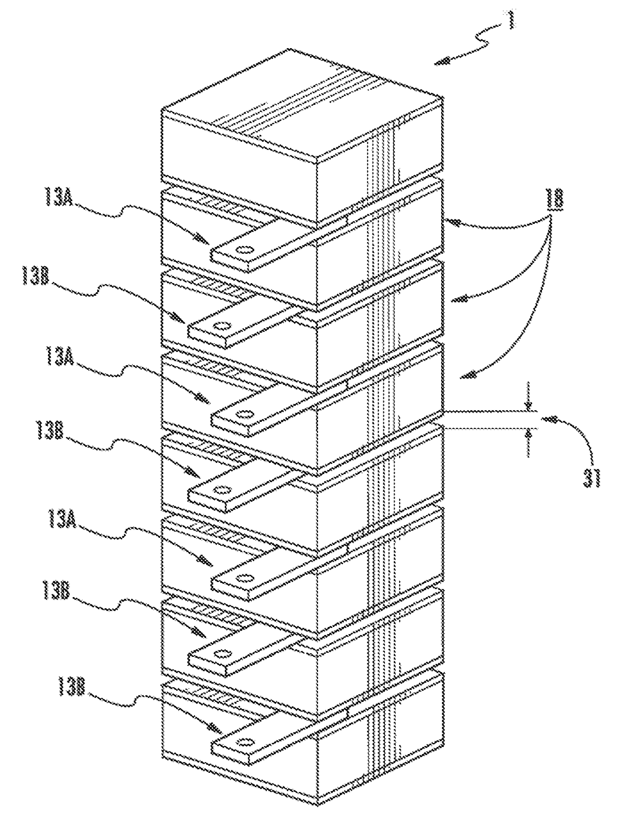
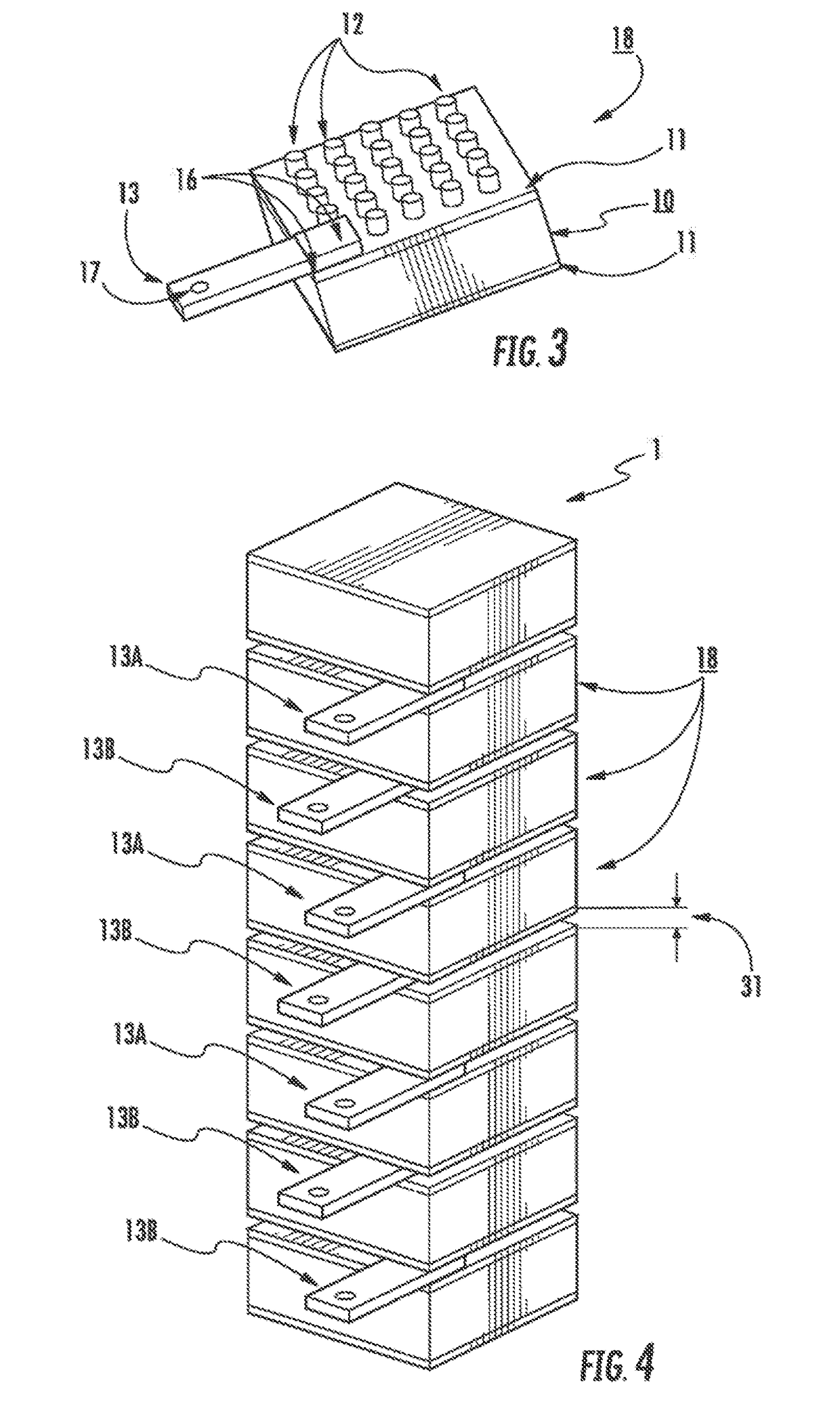
[0061]Reference will now be made in detail to embodiments of the invention. Wherever possible, same or similar reference numerals are used in the drawings and the description to refer to the same or like parts or steps. The drawings are in simplified form and are not to precise scale. The words ‘couple’ or ‘bond’ or ‘glue’ or ‘attach’ and similar terms do not necessarily denote direct and immediate connections, but also include connections through intermediate elements or members or devices. For purposes of convenience and clarity only, directional (up / down, etc.) or motional (forward back, etc.) terms may be used with respect to the drawings. These and similar directional terms should not be construed to limit the scope in any manner. It will also be understood that other embodiments may be utilized without departing from the scope of the present invention, and that the detailed description is not to be taken in a limiting sense, and that elements may be differently positioned, or ...


PUM


Abstract

A system and method provides a piezoelectric stack arrangement for reduced driving voltage while maintaining a driving level for active piezoelectric materials. A stack arrangement of d36 shear mode <011>single crystals of both air X-cut and Y-cut ±1:45° (±20°) arrangement are bonded with discrete conductive pillars to form a shear crystal stack. The bonding area between the neighboring crystal parts is minimized. The bonding pillars are positioned at less than a total surface are of the single crystal forming the stack. The stack fabrication is facilitated with a precision assembly system, where crystal parts are placed to desired locations on an assembly fixture for alignment following the preset operation steps. With the reduced clamping effect from bonding due to lower surface coverage of the discrete conductive pillars, such a piezoelectric d36 shear crystal stack exhibits a reduced driving voltage while maintaining a driving level and substantial and surprisingly improved performance.

Description

CROSS REFERENCE TO RELATED APPLICATIONS[0001]This application relates to and claims priority from U.S. Prov. Ser. No. 61 / 989,099 filed May 6, 2014 and U.S. Prov. Ser. No. 61 / 989,118 filed May 6, 2014, the entire contents of each are incorporated herein by reference.[0002]This application also relates to and is a continuation-in-part of, U.S. application Ser. No. 14 / 266,229, filed Apr. 30, 2014 (pending), which in turn is a continuation of and claims priority to U.S. application Ser. No. 13 / 957,074 filed Aug. 1, 2013 and issued as U.S. Pat. No. 8,728,238 on May 20, 2014, the entire contents of which are incorporated herein by reference; which claims priority to and is a continuation of U.S. application Ser. No. 12 / 373,080 filed Jan. 9, 2009, now U.S. Pat. No. 8,535,442 issued Sept. 17, 2013, which claims priority from PCT App. Ser. No. PCT / US07 / 073412 filed Jul. 12, 2007 which clams priority from U.S. Prey. App. Ser. No. 60 / 830,139, filed Jul. 12, 2006, the entire contents of each of...

Claims


Application Information

Patent Timeline
Patent Type & Authority Applications(United States)
IPC IPC(8): H01L41/083H01L41/047H01L41/277H01L41/18H01L41/09
CPCH01L41/083H01L41/18H01L41/0471H01L41/277H01L41/0986C30B11/001C30B11/08C30B35/00Y10T117/10Y10T117/1008Y10T117/1024Y10T117/1076Y10T117/108Y10T117/1092C30B29/22H10N30/85H10N30/50H10N30/057
Inventor HAN, PENGDITIAN, JIANDYNAN, STEPHENSTONE, BRANDON
Owner CTS CORP ELKHART
Why Eureka
Try Eureka