
Compact hybrid laser rod and laser system

Active Publication Date: 2017-06-29
COHERENT APPL +1
View PDF3 Cites 1 Cited by
  • Summary
  • Abstract
  • Description
  • Claims
  • Application Information

AI Technical Summary

Benefits of technology

The patent text describes a new type of laser rod that can function both as a laser and a laser amplifier. This new rod has a unique design that combines the high efficiency and high quality of fiber lasers with the increased power and energy levels of solid-state lasers. The challenge of meeting the stringent requirements for deployment to space and other operating environments is being solved by this new design. Essentially, this new rod offers an efficient and effective solution for achieving the desired attributes of tunable laser beams at higher power levels.

Problems solved by technology

Achieving the superb attributes of tunable laser beams at increasingly high power levels, while meeting the stringent mass, power, and reliability for deployment to space and other operating environments, presents challenges that are not presently met by many solid-state lasers.

Method used


Image

  • Compact hybrid laser rod and laser system
  • Compact hybrid laser rod and laser system
  • Compact hybrid laser rod and laser system

Examples


Embodiment Construction

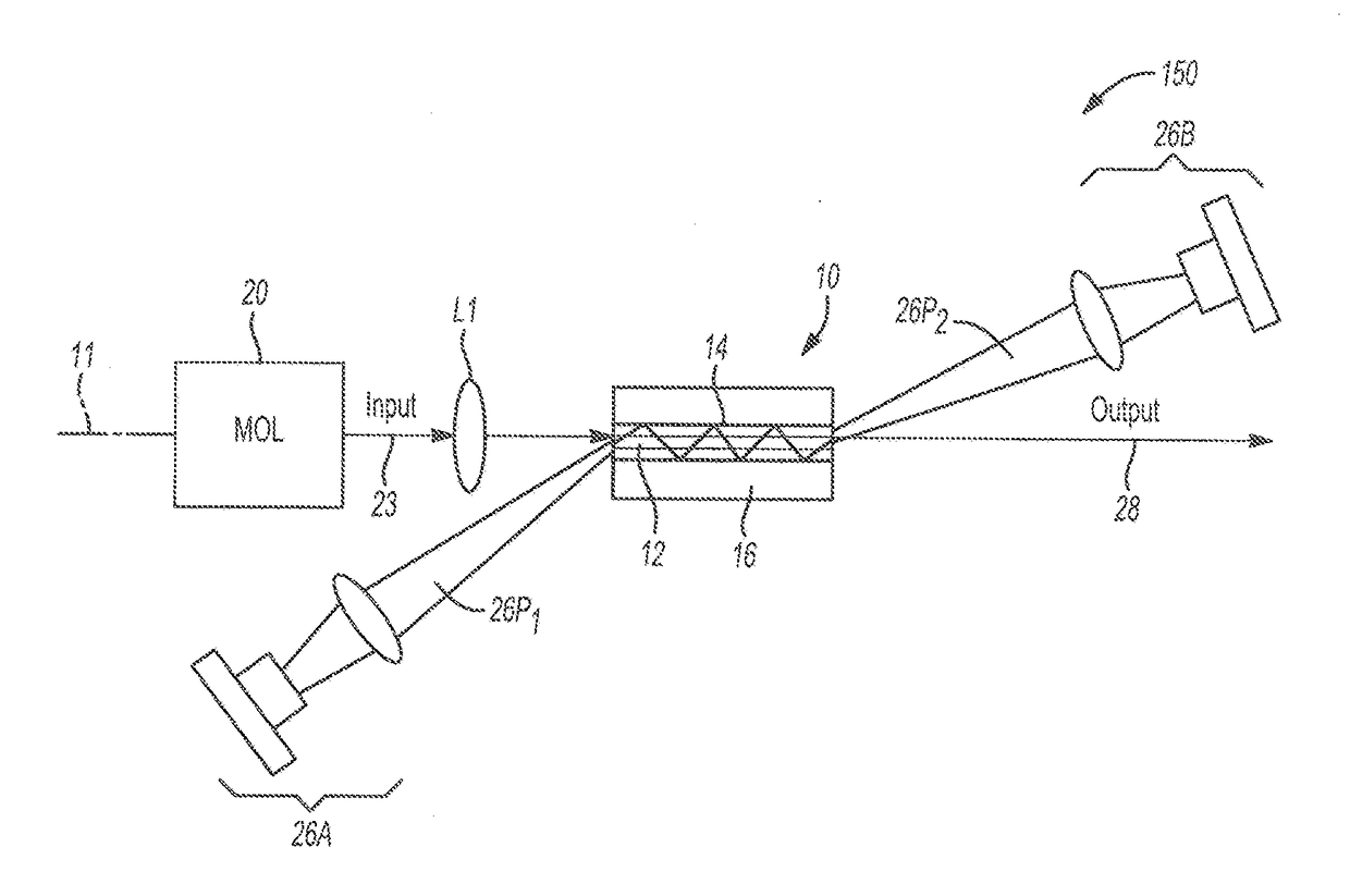
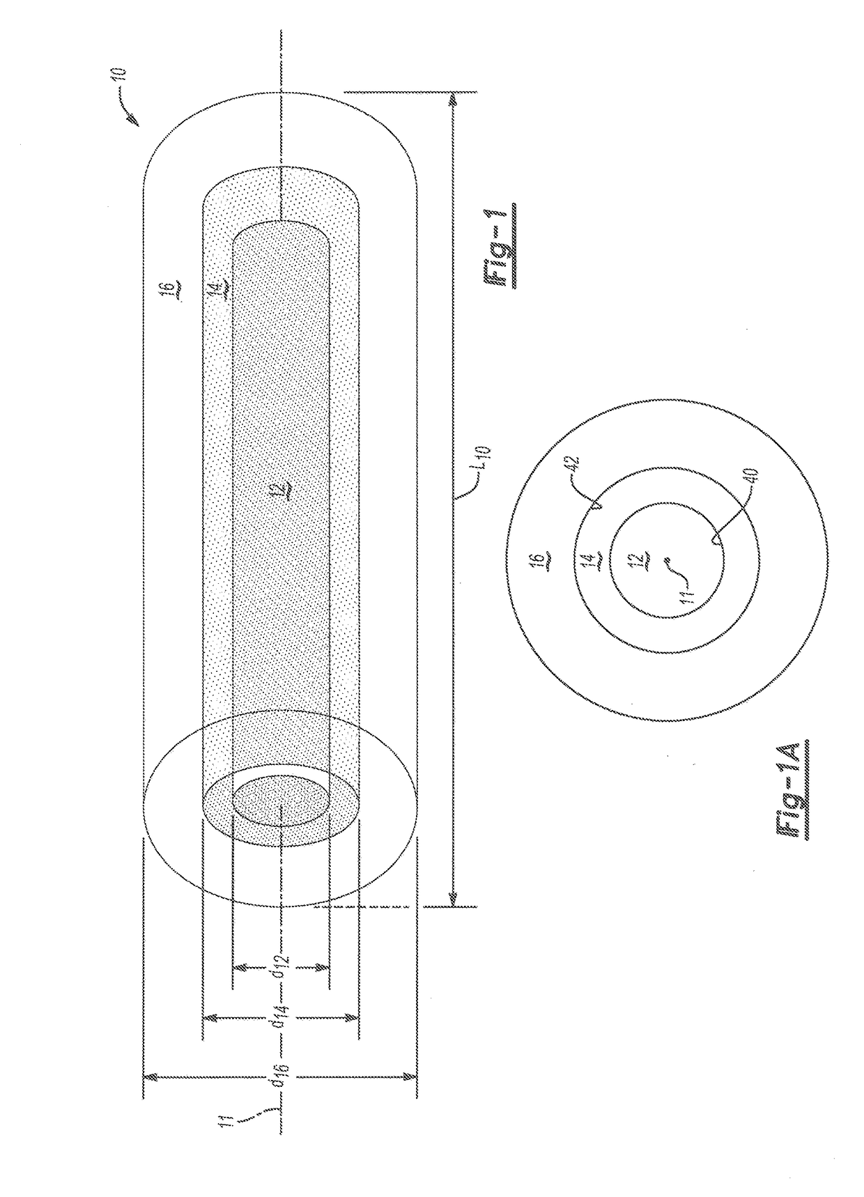
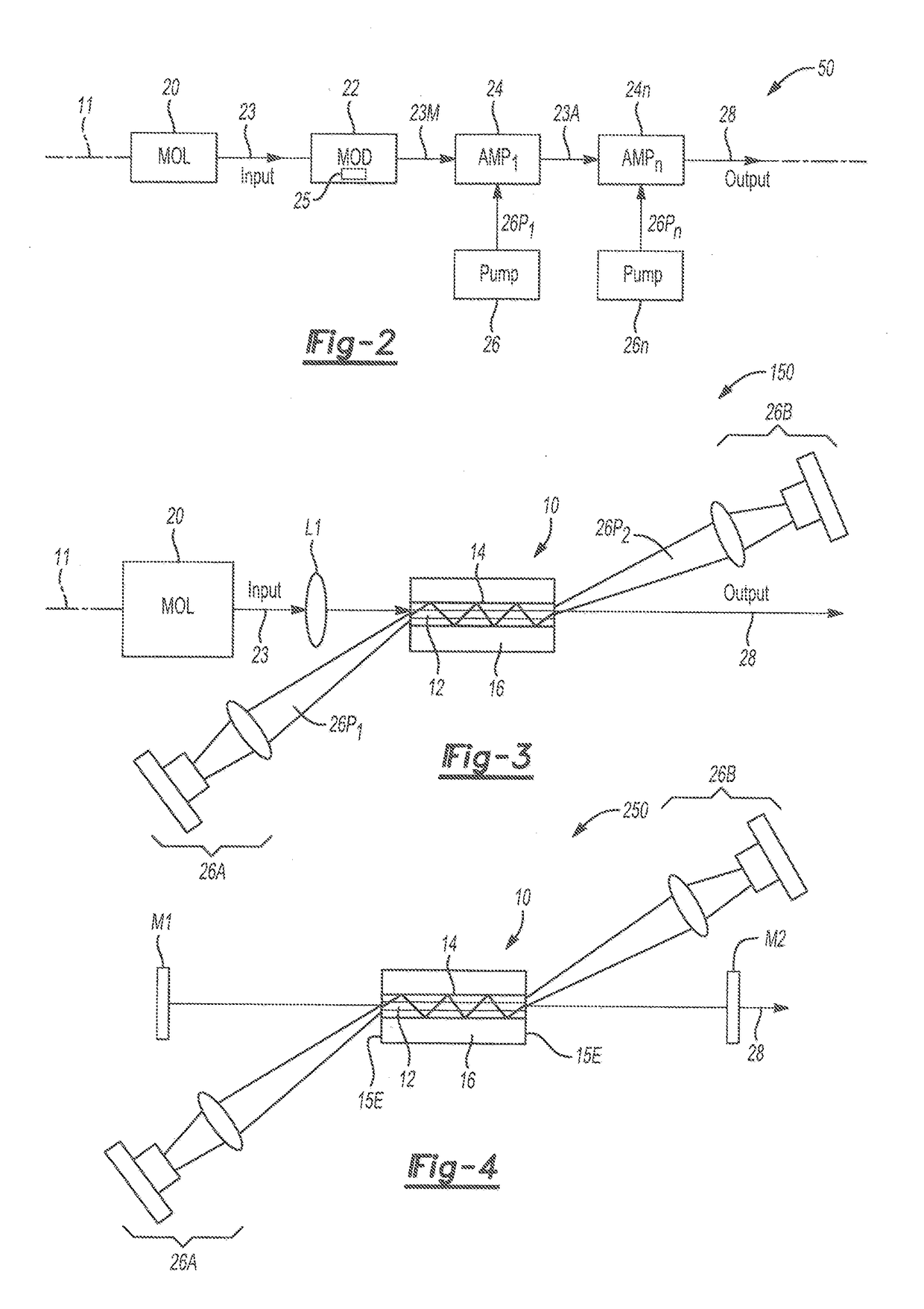
[0023]For purposes of description herein, the terms “upper,”“lower,”“right,”“left,”“rear,”“front,”“vertical,”“horizontal,” and derivatives thereof shall relate to orientation shown in FIG. 1. However, it is to be understood that various alternative orientations and step sequences may be envisioned, except where expressly specified to the contrary. Also for purposes of the present detailed description, words of approximation such as “about,”“almost,”“substantially,”“approximately,” and the like, may be used herein in, the sense of “at, near, or nearly at,” or “within 3-5% of,” or “within acceptable manufacturing tolerances,” or any logical combination thereof. It is also to be understood that the specific devices and processes illustrated in the attached drawings, and described in the following specification, are exemplary embodiments of the inventive concepts defined in the appended claims. Hence, specific dimensions and other physical characteristics relating to the embodiments dis...


PUM


Abstract

A hybrid fiber rod includes a fiber core and inner and outer cladding layers. The core is doped with an active element. The inner cladding layer surrounds the core, and has a refractive index substantially equal to that of the core. The outer cladding layer surrounds the inner cladding layer, and has a refractive index less than that of the core and inner cladding layer. The core length is about 30 to 2000 times the core diameter. A hybrid fiber rod laser system includes an oscillator laser, modulating device, the rod, and pump laser diode(s) energizing the rod from opposite ends. The rod acts as a waveguide for pump radiation but allows for free-space propagation of laser radiation. The rod may be used in a laser resonator. The core length is less than about twice the Rayleigh range. Degradation from single-mode to multi-mode beam propagation is thus avoided.

Description

CROSS-REFERENCE TO RELATED PATENT APPLICATION(S)[0001]This patent application claims the benefit of and priority to U.S. Provisional Patent Application No. 62 / 271,453, filed on Dec. 28, 2015, the contents of which are hereby incorporated by reference in their entirety.STATEMENT REGARDING FEDERALLY SPONSORED RESEARCH OR DEVELOPMENT[0002]The invention described herein was made in the performance of work under a NASA contract and by employees of the United States Government and is subject to the provisions of Public Law 96-517 (35 U.S.C, §202) and may be manufactured and used by or for the Government for governmental purposes without the payment of any royalties thereon or therefore. In accordance with 35 U.S.C. §202, the contractor elected not to retain title.BACKGROUND OF THE INVENTION[0003]Lasers emit concentrated light via the optical amplification and stimulated emission of electromagnetic radiation, which in turn occurs through an application-specific laser gain medium. The light...

Claims


Application Information

Patent Timeline
IPC IPC(8): H01S3/067H01S3/094H01S3/16H01S3/0941
CPCH01S3/06708H01S3/06733H01S3/1603H01S3/094003H01S3/0941H01S3/094049H01S3/09415H01S3/2308H01S3/2316H01S3/061H01S3/0612H01S3/0617H01S3/161H01S3/1608H01S3/1611H01S3/06754
Inventor BUSCH, GEORGE E.AMZAJERDIAN, FARZINPIERROTTET, DIEGO F.
Owner COHERENT APPL
Learn More