Compartmentalized heat exchanger in industrial component system

a heat exchanger and industrial component technology, applied in the field of industrial equipment, can solve the problems of degrading the performance of electrical components, increasing the temperature of the assembly, and generating significant amounts of heat, so as to reduce the heat within the primary compartment, effectively maintain the component, and reduce the operation of the heat generating industrial component

Inactive Publication Date: 2017-06-29
STOCKDALE JOHN
View PDF10 Cites 3 Cited by
  • Summary
  • Abstract
  • Description
  • Claims
  • Application Information

AI Technical Summary

Benefits of technology

[0012]The containerized heat generating industrial component system of the present invention comprises at least one heat generating industrial component mounted within a primary compartment. The primary compartment shares a wall with an isolated access compartment. The at least one heat generating industrial component includes a heat exchanger or heat sink mounted on one surface thereof, and is mounted in such a way that the heat exchanger or heatsink is mounted through the wall which is shared between the primary compartment and the isolated access compartment, so that the at least one heat generating industrial component is located within the primary compartment, and the related heat exchanger is located within the corresponding isolated access compartment. Heat can then be drawn off of the heat generating industrial component, such as the VFD or the like, via the isolated access compartment. Heat within the primary compartment is minimized, and operation of the heat generating industrial component can continue if there is ever any reason to clean or access the heat exchanger via the isolated access compartment.
[0013]The present application discloses a novel heat sink arrangement where the heat sink is located in a compartment separate from and adjacent to the component that it cools, and yet maintains sufficient thermal contact with the component to be able to effectively maintain the component within a desired temperature range during operation. This novel arrangement allows for cleaning of the heat sink without having to shut down or otherwise take offline the component that the heat sink serves. Operating heat within the primary compartment is also minimized by the protrusion of the heat exchanger into a separate operating area outside of the primary compartment.
[0014]Various types of ventilation can be placed within the isolated access compartment—vents, grills or the like allowing for the passage of air in either a passive or forced fashion there across. It is specifically contemplated that powered blowers could be used to blow a maximum volume of air through the isolated access compartment and maximize the cooling ability of the heat exchanger.

Problems solved by technology

As these electronic assemblies have become more complex, with higher processor speeds, higher operating frequencies, smaller size, and complex power management arrangements, significant amounts of heat can be generated.
This heat presents a problem as undissipated it leads to increased temperature in the assembly.
Excessive heat can degrade the performance of electrical components, decrease reliability and potentially lead to component failure.
An inherent limitation of heat sink arrangements is that over time the efficiency of the heat sink can degrade as a result of accumulation of dust, dirt and other contaminants.
These contaminants create a barrier between the heat sink material and the cooling medium, thereby reducing the efficiency of heat transfer away from the component being cooled to the cooling medium.
This is a particularly serious problem when components are being operated in challenging environments that have significant contamination with airborne particles, such as occurs in mining operations and the like.
The use of these power sleds is often in very challenging work environments, maximizing the number of occurrences for necessary cleaning of a heat exchanger on the VFD in question.
These are typically also very high voltage work applications where safety being paramount, it is simply not possible to operate the VFD when there is any human access to the components thereof, which would be required when cleaning was undertaken.
Prior art heat sink arrangements suffer from a problem in that the components being cooled are in the same physical compartment as the heat sink; and so in order to clean the heat sink, it is prudent if not essential to turn off the electronic components in order to avoid inadvertent damage during the cleaning process, especially when it is necessary to use cleaning agents that are electrical conductors.

Method used


Image

  • Compartmentalized heat exchanger in industrial component system
  • Compartmentalized heat exchanger in industrial component system
  • Compartmentalized heat exchanger in industrial component system

Examples


Embodiment Construction

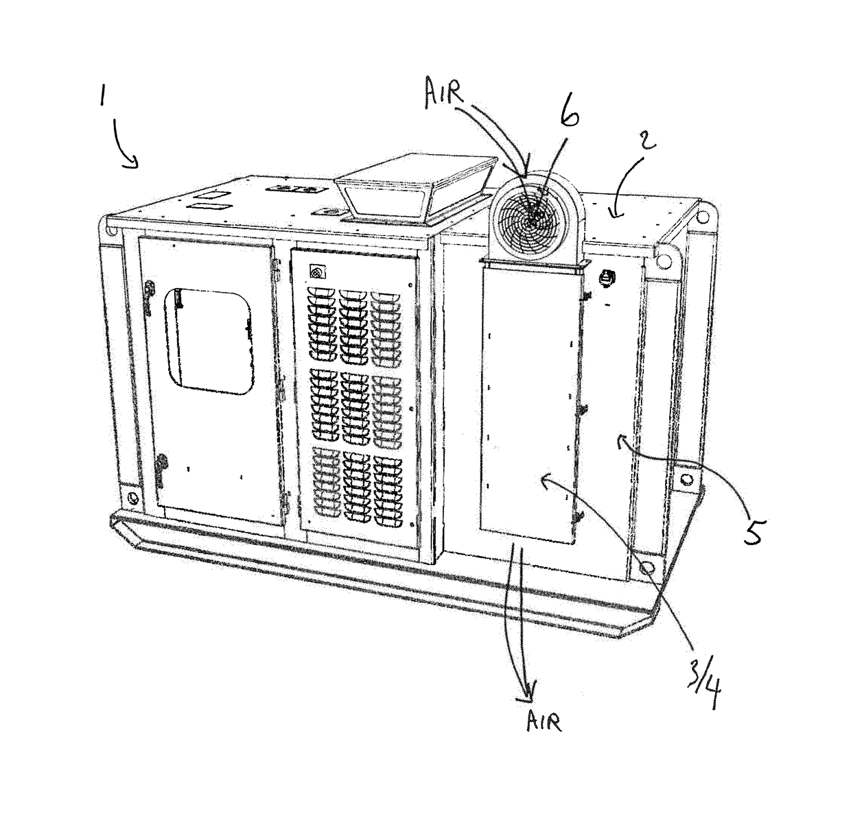
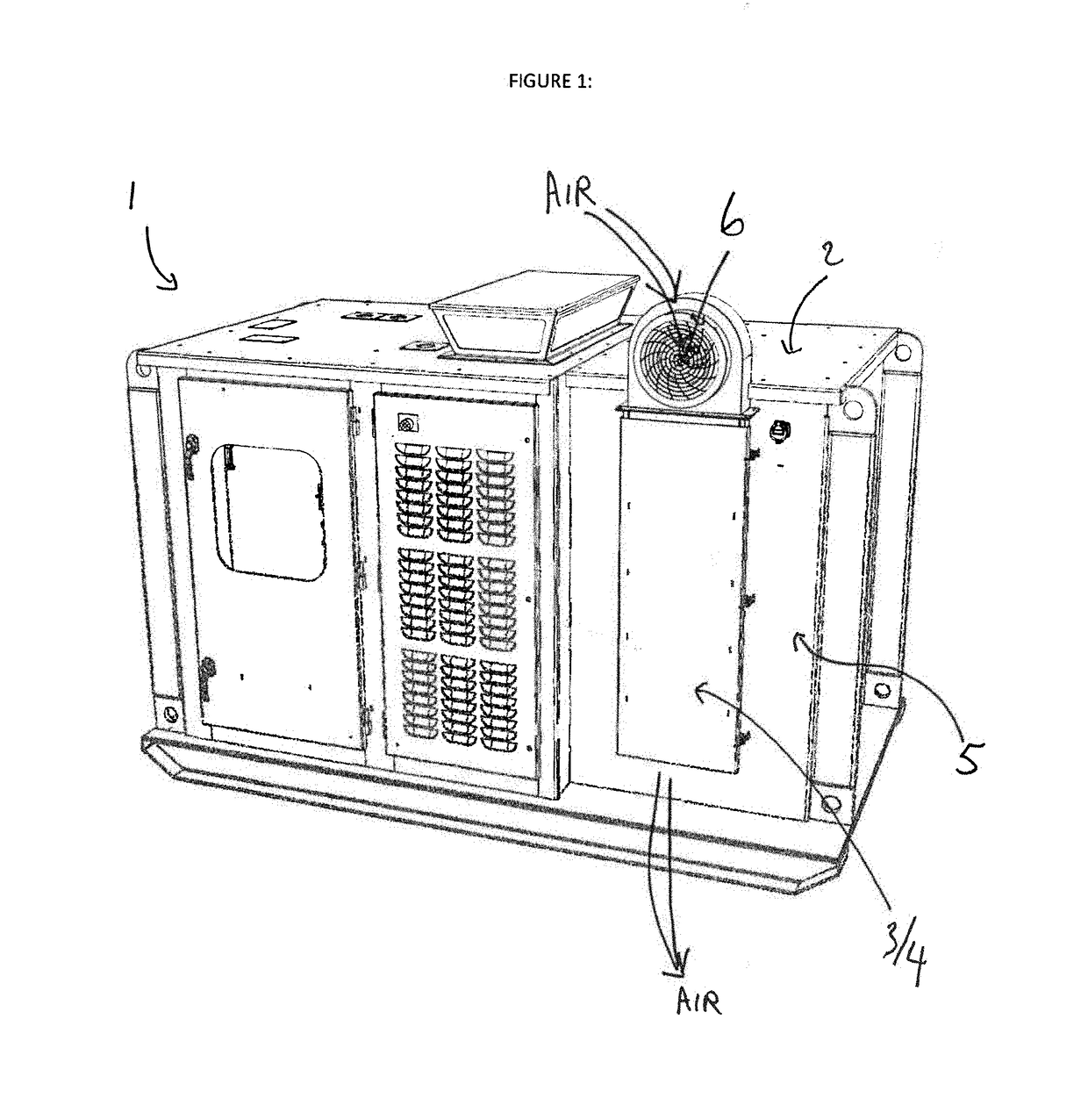
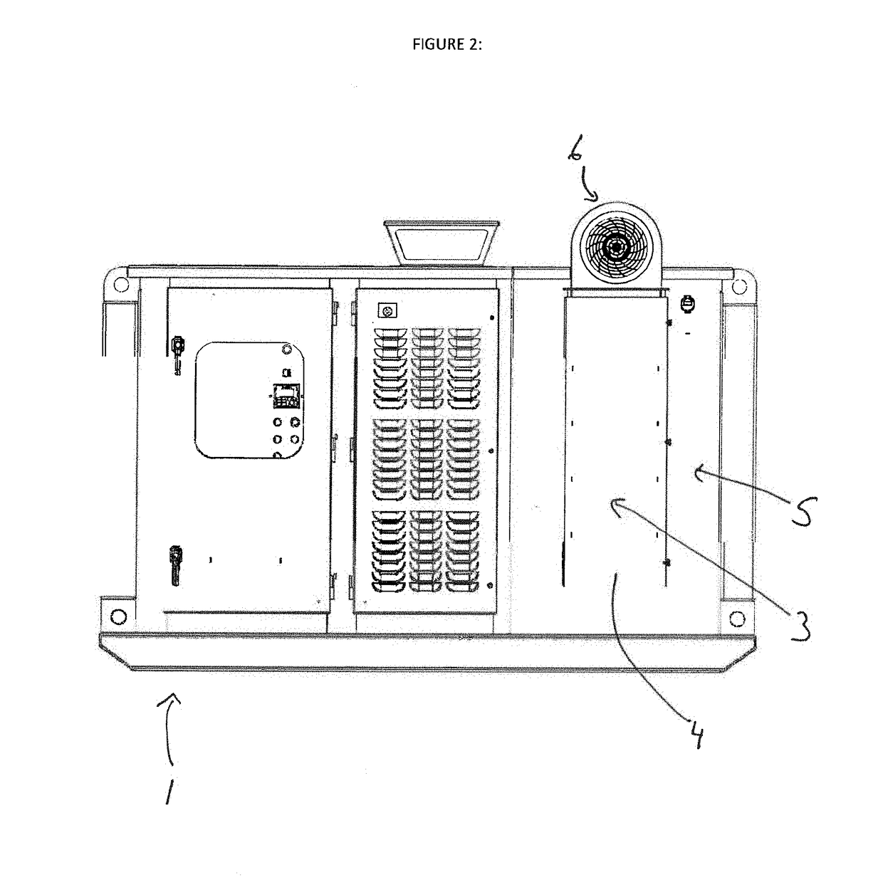
[0024]As outlined above, the present invention relates to a novel compartmentalized heat exchanger in a heat producing industrial component system. Various types of industrial component systems would include heat producing industrial components, such as an electric drive, variable frequency drive or VFD, or any other type of a mechanical or electrical component which generates heat in operation. Some heat producing industrial components might be cooled by providing a flow of a cooling media that contacts the surface of the heat exchanger. The cooling media may be fluid, where others, which are the focus of the present invention, where one or more vane heat exchangers or heat sinks attached to the surface thereof are cooled by a flow of air as the cooling medium. A plurality of vanes on the heat exchanger allows for increased efficiency in the dissipation of heat from the operation of the component into the surrounding environment.

[0025]The at least one heat producing industrial comp...


PUM

PropertyMeasurementUnit
temperatureaaaaaaaaaa

Abstract

In a cooled component system, a heat exchanger mounted on a surface of the industrial component is housed in an isolated access compartment adjacent to but separated from the primary compartment containing the industrial component. Housing the heat exchanger in a separately accessible compartment permits access to the heat exchanger for cleaning or other purposes without having to shut down the industrial component being cooled. A means for moving a cooling media over the surface a the heat exchanger might also be included to maximize heat exchange.

Description

FIELD OF THE INVENTION[0001]This invention is in the field of industrial equipment which produces heat in operation requiring heat evacuation or exchange, and more specifically relates to heat exchangers or “heat sinks” configured to manage heat produced from such a source.BACKGROUND[0002]Electrical components such as microprocessors, motor drives and voltage regulators produce heat as part of their normal operation. One of the types of components which are in this category are variable frequency drives (also known in industry as VFDs). As these electronic assemblies have become more complex, with higher processor speeds, higher operating frequencies, smaller size, and complex power management arrangements, significant amounts of heat can be generated. This heat presents a problem as undissipated it leads to increased temperature in the assembly. Excessive heat can degrade the performance of electrical components, decrease reliability and potentially lead to component failure. As a ...

Claims


Application Information

Patent Timeline
Patent Type & Authority Applications(United States)
IPC IPC(8): H05K7/20F28F19/04F28F27/00F28F9/00
CPCH05K7/2039F28F9/001F28F2009/004F28F27/00H05K7/20136F28F19/04H05K7/20918
Inventor STOCKDALE, JOHN
Owner STOCKDALE JOHN
Why Eureka
Try Eureka