Autonomous working machine such as autonomous lawn mower

a working machine and lawn mower technology, applied in the field of autonomous working machines, can solve the problems of not being able to achieve the effect of achieving the effect of achieving the effect of achieving the effect of achieving the effect of achieving the effect of achieving the effect of achieving the effect of achieving the effect of achieving the effect of achieving the effect of achieving the effect of achieving a high degree of automation, ensuring the effect of automatic operation and ensuring the accuracy of the

Active Publication Date: 2017-07-06
HONDA RES INST EUROPE
View PDF5 Cites 21 Cited by
  • Summary
  • Abstract
  • Description
  • Claims
  • Application Information

AI Technical Summary

Benefits of technology

[0009]It is now an object of the present invention to improve the performance of autonomous working machines by estimating a current position of the autonomous working machine more reliably and with sufficient precision without employing systems that cause high costs. Of course there is technology available that is sufficiently precise but such systems cause costs which are not acceptable in the market of such autonomous lawn mowers or the like.

Problems solved by technology

In most cases this could not be achieved without unnecessary movements and unnecessary driving paths of the autonomous working machine, because the machine is driving randomly around.
Obviously such random drive is not very efficient regarding the power consumed by the autonomous lawn mower until the entire area is mowed.
With increased driving distance this deviation will typically increase and lead to mowing results that are not satisfying.
Another problem is that rate encoders may not give reliable results due to wheel slip for example.
On the other side IMUs have a strong drift over time which for example causes problems in case of long parallel drive ways.
Thus, even if the drive commands are corrected on the basis of an estimated position of the mower the low accuracy of the position estimation makes it impossible to control the mower following the intended path or pattern precisely.
But one problem still is that even here the basis for the correction signal is still derived by using rate encoders.
Of course there is technology available that is sufficiently precise but such systems cause costs which are not acceptable in the market of such autonomous lawn mowers or the like.
Thus, the accuracy of the position determination is reduced when constant time gaps are used.

Method used


Image

  • Autonomous working machine such as autonomous lawn mower
  • Autonomous working machine such as autonomous lawn mower
  • Autonomous working machine such as autonomous lawn mower

Examples


Embodiment Construction

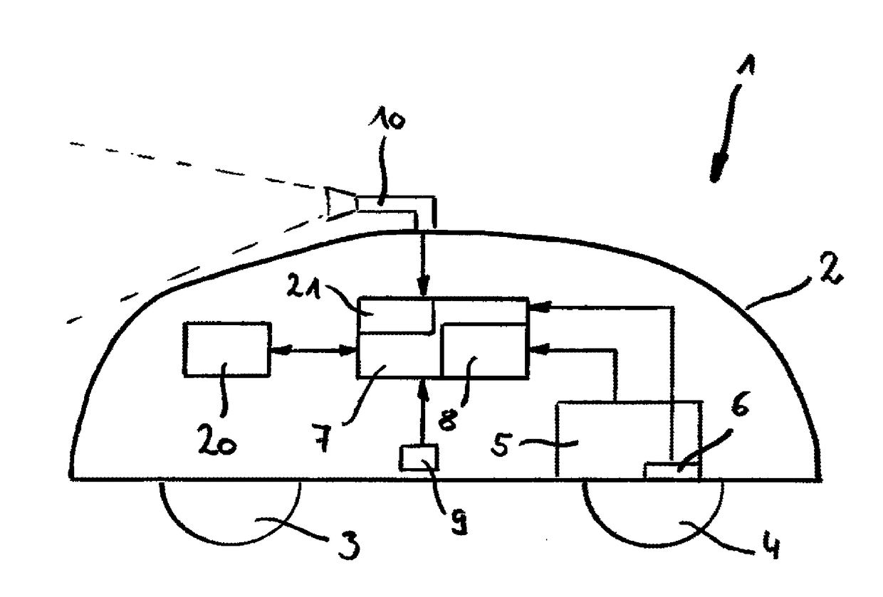
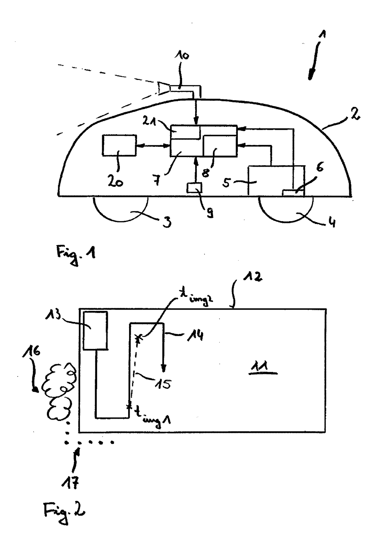
[0027]A schematic of an autonomous lawn mower 1 according to an embodiment of the present invention is illustrated in FIG. 1. It is to be noted that any information and detail of the invention described with respect to the autonomous lawn mower of course might also be used in other autonomous working machines such as scarifiers, vacuum cleaners and the like.

[0028]The autonomous lawn mower 1 comprises a housing 2 housing most of the components that are necessary for fulfilling the mowing operation and the autonomous driving of the mower. In particular the housing 2 also supports drive wheels 3, 4. For controlling speed of the autonomous lawn mower 1 usually rear wheels 4 are driven by a driving means. In order to control the speed and direction of the autonomous lawn mower 1 the driving means comprises an electric motor 5 for each of two rear wheels 4. Both of the electric motors 5 can be controlled individually. Thus, the rotation of the left and the right rear wheel 4 can also be c...


PUM


Abstract

The invention regards an autonomous working machine comprising drive means, current position estimation means, control means including a driving control unit and a camera. With aid of the current position estimation means the current position of the autonomous working machine is estimated. Furthermore, the driving control unit generates driving commands for the driving means on the basis of an intended movement of the autonomous working machine and the estimated current position. The camera is configured to capture images of the environment of the working machine. For estimating the current position, the current position estimation means is formed by the control means, which is configured to apply visual odometry on the captured images for estimating the current position of the working machine.

Description

BACKGROUND[0001]Field[0002]The invention regards an autonomous working machine such as an autonomous lawn mower or scarifier comprising driving means for self-propelled driving, current position estimation means, control means including a driving control unit for generating driving commands for the driving means on the basis of which a driving direction and driving speed is adjusted, and a camera that is configured to capture images of an environment of the working machine.[0003]Description of the Related Art[0004]In order to increase the comfort for people who have to do for example gardening various working machines have been developed over the last decades. A more recent development in order to further increase the comfort is that such working machines are self-propelled which means they have the capability to move on a lawn being driven by for example an electric motor and without the gardener needing to push the working machine. Nevertheless for quite a while it was still neces...

Claims


Application Information

Patent Timeline
Patent Type & Authority Applications(United States)
IPC IPC(8): A01D34/00G06T7/70G05D1/02H04N13/02H04N7/18B60R11/04G06K9/00
CPCA01D34/008B60R11/04G06T7/70G06K9/00791H04N13/0203H04N7/183G05D2201/0208G05D1/0272G05D1/027A01D2101/00G06T2207/10012G06T2207/30252G05D1/0251G05D1/0253H04N13/204G06V20/56
Inventor EINECKE, NILSFRANZIUS, MATHIASDEIGMOLLER, JORG
Owner HONDA RES INST EUROPE
Why Eureka
Try Eureka