
System and method for non-binding allograft subtalar joint implant

a technology of allograft and subtalar joint, which is applied in the field of medical procedures, can solve the problems of abnormal translation of forces placed on the surrounding joints, hammertoes, and shin splints, and achieve the effect of reducing the tendency for abnormal motion

Active Publication Date: 2017-07-06
ARTHROSURFACE
View PDF34 Cites 34 Cited by
  • Summary
  • Abstract
  • Description
  • Claims
  • Application Information

AI Technical Summary

Benefits of technology

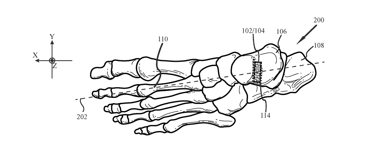
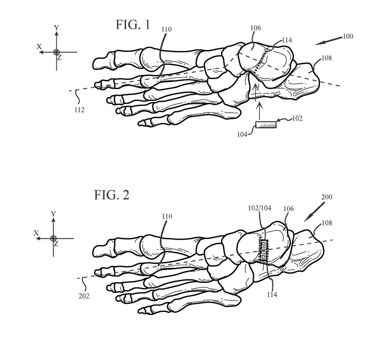
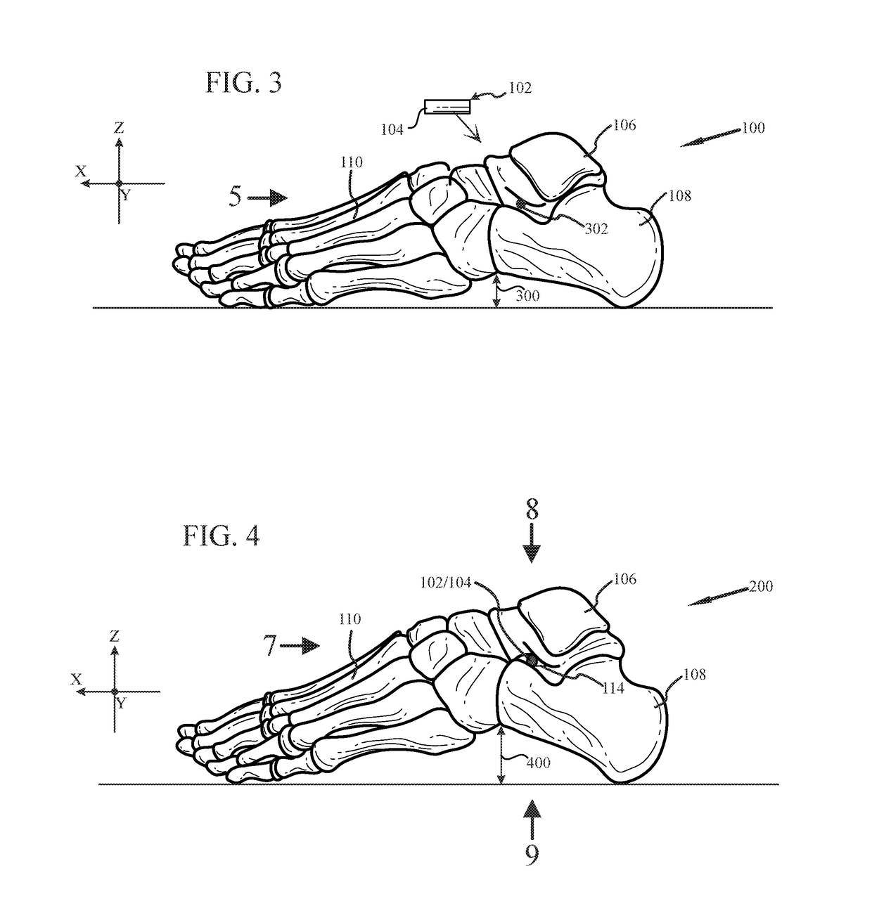
The patent describes a non-binding allograft implant for replacing a person's subtalar joint. The implant is made from a reticular dermis element that is harvested from a donor and processed to remove cellular components. The resulting material is a flexible and compressible rod that is designed to fit snuggly between the talus and calcaneus bones. The implant helps maintain the natural alignment of the bones and reduces abnormal motion during normal foot use. The technical effect of this invention is to provide a safe and effective treatment for subtalar joint replacement.

Problems solved by technology

As there is a biomechanical relationship between the foot and lower leg, problematic issues in the inner workings of the foot structure adversely affect the rest of the body.
Moreover, in addition to being painful, pathologic flatfeet may cause bunions, hammertoes, heel spurs, arch pain, growing pains, shin splints, knee pain, and back pain.
When the subtalar joint's relaxed position is no longer in the intended neutral position, then the translation of forces placed on the surrounding joints, ligaments and osseous structures is abnormal.
While this can be demonstrated by physically manipulating a person's foot, such physical manipulation is impractical during a normal use of the foot.
While perhaps effective at reestablishing an improved alignment of the talus and calcaneus bones the options for implants known to date fall short of truly reestablishing the triplanar motion and naturally gliding motion of the subtalar joint.
In addition, the metal nature of the Maxwell implant results in the patient experiencing a hard stop—the foot simply does not move in some directions and the resistance to compression can be painful.
In addition, over time and as a result of repeated use of the repaired foot, the Maxwell implant may actually abrade, or cause the surrounding bone tissues to abrade—leading to shards of foreign or natural material within the subtalar joint further causing pain and perhaps requiring surgical extraction of the debris, and / or the Maxwell implant itself as suggested by the title.
As such, the motion of the foot may be un-natural and perhaps painful for some person's, and once again shards of natural and foreign materials may develop within the subtalar joint resulting in pain and the need for surgical extraction.
The Graham implant is also taught to be constructed of by a polymer which is substantially incompressible and tough, once again potentially resulting in an uncomfortable if not painful implant for some person's.
And again, the binding nature of the Graham implant may once again result in shards of foreign or natural material within the subtalar joint.
The stress and force imparted by this unnatural elimination may and often does cause abrasion of implant and or bone tissue.
While perhaps avoiding the bound alignment imposed by a threaded implant, the tie line may cause insult and abrasion to the tendon as compressive forces upon the conical shaped body result in the generation of lateral forces upon the plug and thereby tension the tie line.
Further, the plastic may still abrade or cause the talus and calcaneus bones to abrade.
Moreover, although there are a growing number of implants and procedures which strive to alleviate some of the issues associated with flatfoot by stabilizing the subtalar joint, in the main they appear to sacrifice the natural and expected gliding motion of the joint for improved relative spacing.
In addition, as this reduced natural and expected gliding motion is known to often cause abrasion, extraction and replacement of the implants appears to be an expected likelihood in the future, subjecting the patient to an additional surgical procedure as well as potential pain and discomfort when and if the implant breaks down or abrades body tissues.

Method used


Image

  • System and method for non-binding allograft subtalar joint implant
  • System and method for non-binding allograft subtalar joint implant
  • System and method for non-binding allograft subtalar joint implant

Examples


Embodiment Construction

[0031]Our invention solves the problems of the prior art by providing novel systems and methods for a non-binding allograft subtalar joint implant

[0032]Before proceeding with the detailed description, it is to be appreciated that the present teaching is by way of example only, not by limitation. The concepts herein are not limited to use or application with a specific system or method for a non-binding allograft subtalar joint implant. Thus, although the instrumentalities described herein are for the convenience of explanation shown and described with respect to exemplary embodiments, it will be understood and appreciated that the principles herein may be applied equally in other types of systems and methods involving or pertaining to a non-binding allograft subtalar joint implant.

[0033]This invention is described with respect to preferred embodiments in the following description with reference to the Figures, in which like numbers represent the same or similar elements. Further, wi...


PUM

PropertyMeasurementUnit
diameteraaaaaaaaaa
diameteraaaaaaaaaa
diameteraaaaaaaaaa

Abstract

Provided is a system and method for providing a non-binding allograft subtalar joint implant for surgical implant into a person's foot proximate to the ankle. This system for repair includes at least one sterile non-binding allograft subtablar joint implant provided as a pre-formed allograft rod plug “ARP” having a diameter about equal to an average width of a canal between a person's talus and calcaneus bones, the ARP being resiliently compressible and flexible. When snuggly disposed between the person's talus and calcaneus bones, the ARP compresses during normal use of the person's foot and maintains the canal in an anatomically correct alignment and reduces a tendency for abnormal motion between the person's talus and calcaneus bones. An associated method of use is also provided.

Description

FIELD OF THE INVENTION[0001]The present invention relates generally to systems and methods for a medical procedure involving an implant for the correction of skeletal misalignment, and more specifically to a non-binding allograft rod plug implant for the subtalar joint to stabilize relative alignment between the talus and calcaneus bones of the human foot.BACKGROUND[0002]A fallen arch or flatfoot is a deformity that affects people young and old. It is a skeletal misalignment deformity in which the arches of the foot collapse resulting in the entire sole of the foot being in complete or nearly complete contact with the ground. As there is a biomechanical relationship between the foot and lower leg, problematic issues in the inner workings of the foot structure adversely affect the rest of the body.[0003]In proper operation the structure of a healthy arch provides an elastic connection between the hind foot and forefoot which serves to safeguard the body during weight bearing activiti...

Claims


Application Information

Patent Timeline
Patent Type & Authority Applications(United States)
IPC IPC(8): A61F2/42A61L27/36
CPCA61F2/4202A61L27/3683A61F2002/4223A61F2002/4207A61L27/362A61F2002/30224A61F2002/30293A61F2002/30971A61F2310/00365
Inventor WERBER, BRUCESUDDARTH, TERRELLSCHOENHAUS, HEROLD
Owner ARTHROSURFACE
Learn More