Unlock instant, AI-driven research and patent intelligence for your innovation.

Distributed electric ducted fan wing

a technology of electric ducted fans and ducted wings, which is applied in the direction of airflow influencers, efficient propulsion technologies, transportation and packaging, etc., can solve the problems of not taking full advantage of the blown upper surface potential, the angle of air flowing over the wing is not uniform over the wing span, and the aircraft is an experimental platform and not a practical vehicle, so as to reduce the weight of the airframe, reduce the effect of turbulence and precise control of the aircra

Active Publication Date: 2017-07-06
ULLMAN DAVID G +1
View PDF1 Cites 7 Cited by
  • Summary
  • Abstract
  • Description
  • Claims
  • Application Information

AI Technical Summary

Benefits of technology

This patent is about combining multiple electric ducted fans with a control system to improve the distribution of lift on the airplanes' wings and other airfoils. The electric ducted fans not only power the airplane but also enhance and control the aerodynamic forces on the lifting surfaces. This results in increased lift, allowing the airplane to fly in a lower drag configuration. The innovation also allows for more precise control of the aircraft, mitigates the effects of turbulence, reduces shed vortices and system failures, and compensates for cross wind during takeoff and landing. Additionally, it may reduce airframe weight and operating costs.

Problems solved by technology

The aircraft was an experimental platform and not a practical vehicle and was abandoned.
Secondly, NASA is leading an effort aimed at small, low speed business, passenger, and general aviation aircraft.
A limitation of the X-57 configuration is that the integration of propulsion with aerodynamics is purely in terms of increasing the speed of the air over both the top and bottom of the wing.
This does not take full advantage of the blown upper surface potential.
Additionally, due to propeller swirl, the angle of attack of air flowing over wing is not uniform over the wing span.
The resulting uneven angle of attack over the span of the wing means that not all sections are flying with the same efficiency in terms of the lift and drag produced.
A final limitation is that a majority of the propulsors are shut down during cruise thus nullifying any potential for propulsion-aerodynamic integration during a majority of the flight envelope.

Method used


Image

  • Distributed electric ducted fan wing
  • Distributed electric ducted fan wing
  • Distributed electric ducted fan wing

Examples


Embodiment Construction

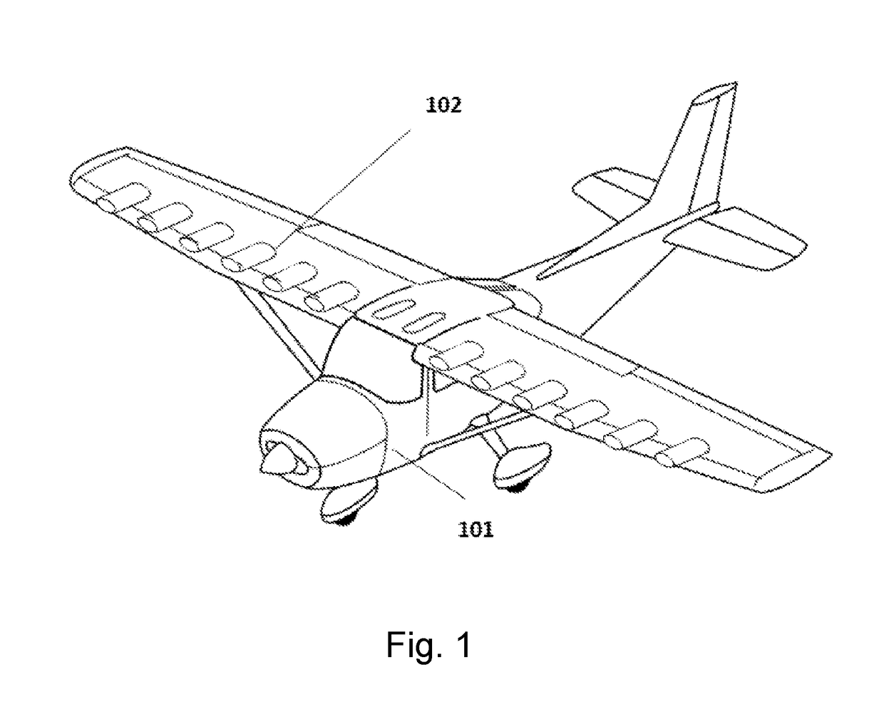
[0034]In FIG. 1, airplane 101 has multiple electric ducted fan (EDF) installations 102 positioned on each aerodynamic surface such as the wing, as shown, and optionally on the horizontal tail. The wing and other horizontal surfaces may be mounted high, shoulder or low and may be of traditional wing-forward-tail-aft, canard or tandem configuration. In this shown embodiment, the airplane has a high wing, a horizontal tail aft, and multiple EDF installations mounted on the wing.

[0035]Four representative embodiments of a cross section of one EDF installation are shown in FIGS. 2a-d, each of which shows a particular embodiment of a single ducted fan 202 integrated into the airfoil shape 201. Ducted fan 202 may be disposed below the wing center line (FIG. 2a), on the center line (FIG. 2b), over it (FIG. 2c) and / or disjoint from it (FIG. 2d). The earlier use of jet turbines restricted the mounting position to above the wings due to the velocity, volume and temperature of the exhaust. Using...


PUM


Abstract

The Distributed Electric Ducted Fan Wing concept incorporates multiple electric ducted fans on lifting surfaces configured to provide integrated aerodynamics and propulsion resulting in enhanced aerodynamic characteristics and thus aircraft performance. The concept uses a plurality of electric ducted fans (EDFs) to not only provide thrust, but to also blow air across the upper surface of a substantial portion of the lifting surface area increasing lift at little loss in efficiency. Not only can the total lift on the surfaces be enhanced, but the lift distribution managed: to aid in aircraft control; ameliorate the effects of turbulence: reduce shed vortices; mitigate the effects of system failures; eliminate stalls; and compensate for crosswinds. This concept offers the potential for increasing electric airplane efficiency and performance, enhancing Short Takeoff and Landing (STOL) capabilities, improving passenger comfort, and reducing the structural stress and cost of aircraft.

Description

CROSS REFERENCE TO RELATED APPLICATIONS[0001]This utility application claims the benefit of U.S. Provisional Patent Application No. 62 / 274,202, filed on Jan. 1, 2016.FIELD OF THE DISCLOSED TECHNOLOGY[0002]The disclosed innovation relates to the integration of thrust and aerodynamics for electrically powered airplanes.BACKGROUND[0003]To date, electric airplane design efforts have focused on replacing small internal combustion engines on motor gliders and ultra light airplanes and with a single electric motor of near equal power. However, electric propulsion offers an opportunity to redesign the aircraft itself and distribute the power about the airframe synergistically enhancing the aerodynamics. Where internal combustion engines are complex and need to be large for efficiency, electric motors are simple and many small ones can be used. The question is; how to make the best use of this distributed potential? This concept directly addresses this question and adds capabilities not poss...

Claims


Application Information

Patent Timeline
IPC IPC(8): B64D27/24B64D29/02B64C3/32B64C3/44B64D31/06
CPCB64D27/24B64C3/44B64D29/02B64C3/32B64D31/06B64C21/00Y02T50/10Y02T50/60Y02T50/40
Inventor ULLMAN, DAVID G.HOMER, VINCENT
Owner ULLMAN DAVID G