Variable frequency oscillator having wide tuning range and low phase noise

a variable frequency oscillator and tuning range technology, applied in the field of wide range voltage control oscillators, can solve problems such as affecting the possibility of achieving, and achieve the effect of wide tuning range and low phase nois

Inactive Publication Date: 2017-07-13
SDRF EURL
View PDF1 Cites 1 Cited by
  • Summary
  • Abstract
  • Description
  • Claims
  • Application Information

AI Technical Summary

Benefits of technology

[0010]It is an object of the present invention to provide a variable frequency oscillator (VFO) or a voltage controlled oscillator (VCO) which allows wide tuning range and low phase noise.

Problems solved by technology

Generally speaking, all those conventional architectures are sensitive to parasitic capacitances which might impair the possibility of achieving, at the same time, a wide tuning range together with a low noise.

Method used


Image

  • Variable frequency oscillator having wide tuning range and low phase noise
  • Variable frequency oscillator having wide tuning range and low phase noise
  • Variable frequency oscillator having wide tuning range and low phase noise

Examples


Embodiment Construction

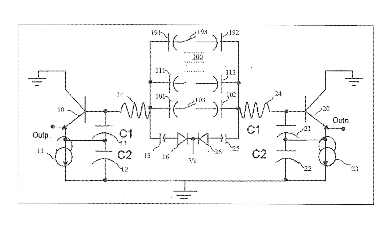
[0026]With respect to FIG. 3, there is now described the general architecture of a variable frequency oscillator (VFO) or voltage control oscillator (VCO) which is well adapted for carrying out the RF circuitry of a communication system, with low phase noise and wide tuning range.

[0027]For the sake of clarity, FIG. 3 shows the arrangement with simplified biasing so as to focus on the main elements of the preferred embodiments.

[0028]The architecture is based on a differential topology comprising a first transistor 10 and a second transistor 20 which, in the embodiment being considered are conventional NPN transistors.

[0029]It should be clear that a skilled man will be able to replace transistors 10 and 20 by other transistors, including FET transistors, MOS transistors etc . . .

[0030]Transistor 10 has an emitter generating a first output signal Outp, a base and a collector. The collector of transistor 10 is connected to a reference voltage, serving as a ground for AC.

[0031]a. The emi...


PUM


Abstract

A variable frequency oscillator comprising a first transistor (10) and a second transistor (20); wherein the first transistor (10) has a first terminal—collector—which is connected to a reference voltage, and a second terminal—emitter—which is connected to a first terminal of a first current source (13), which second terminal is connected to ground, and a third terminal—base—connected to a first terminal of a first inductor (14) and to a top terminal of a first capacitor (11), wherein the first capacitor (11) has a bottom terminal which is connected to the second terminal—emitter—of the first transistor (10) but also to a top terminal of a second capacitor (12) having a bottom terminal being connected to ground;
    • wherein the second transistor (20) has a first terminal—collector—which is connected to a reference voltage, and a second terminal—emitter—which is connected to a first terminal of a second current source (23), which second terminal is connected to ground, and a third terminal—base—connected to a first terminal of a second inductor (14) and to a top terminal of a third capacitor (21), wherein the third capacitor (21) has a bottom terminal which is connected to the second terminal—emitter—of the second transistor (20) and also to a top terminal of a fourth capacitor (22) having a bottom terminal connected to ground;
    • wherein the first and second inductors (14, 24) have a second terminal which are connected via a circuit (100) achieving variable capacitance, so as to form a circuit connecting in series all passive components composing the LC tank, so as to achieve a variable capacitance which can be used for performing a tuning of the oscillator, and
    • wherein the second capacitor (12) and the fourth capacitor (22) are both connected to the physical ground thereby avoiding a 2nd harmonic common mode oscillation that might dominate over the differential fundamental one and might destroy the first and the second transistors (10, 20).

Description

TECHNICAL FIELD[0001]The invention relates to the field of electronics circuits and more particularly to a wide range voltage control oscillator showing low phase noise.BACKGROUND ART[0002]Oscillator circuits play quite an important part in the field of electronics circuits, including communication systems, providing clocking and timing signals in digital circuits and frequency translation in radio frequency (RF) circuits.[0003]Among those oscillators, the well-known Colpitts oscillator is widely used in the field. An example of a Colpitts oscillator is illustrated in FIG. 1A showing a transistor M biased by a current source I and associated with an inductance L and the series combination of C1 and C2 capacitors forming the parallel resonant tank circuit defining the oscillation frequency, in accordance with the formula.f=12πL(C1C2C1+C2)[0004]In the Colpitts circuits, the arrangement of a variable frequency oscillator (VFO) requires the voltage divider to include a variable capacito...

Claims


Application Information

Patent Timeline
Patent Type & Authority Applications(United States)
IPC IPC(8): H03B5/04H03B5/12
CPCH03B5/04H03B5/1231H03B2201/0208H03B2200/004H03B5/124H03B5/1218H03B5/1243H03B2200/0006H03B2200/0008H03L7/099
Inventor BISANTI, BIAGIODUVIVIER, ERICCARPINETO, LORENZOCIPRIANI, STEFANOCOPPOLA, FRANCESCOPUCCIO, GIANNIARTINIAN, REMIMAROT, FRANCOISBEDERO, VANESSAKOECHLIN, LYSIANE
Owner SDRF EURL
Why Eureka
Try Eureka