Heating and cooling device

Active Publication Date: 2017-07-20
FUJI ELECTRIC CO LTD
View PDF5 Cites 24 Cited by
  • Summary
  • Abstract
  • Description
  • Claims
  • Application Information

AI Technical Summary

Benefits of technology

[0042]According to still another aspect described above, when the tray on which the member-to-be-processed is placed is cooled in a state where the tray is in contact with the cooling unit, the pressing unit presses the tray to the cooling unit. This may increase the contact area where the tray is in contact with th

Problems solved by technology

However, in recent years, a power semiconductor module and the like that are employed as, for example, a switching device applied for power conversion purpose are required to use under severe environmental condition.
However, in comparison with the solder material composed of the Sn—Ag based material, the solder material composed of the Sn—Sb based material with highly concentrated Sb has poor properties in solder wettability as a thick oxide is formed on a surface of a member-to-be-soldered.
When using the reflow furnace opening to the atmosphere, surface oxide is not fully reduced on a member-to-be-soldered.
Then a problem is raised so that a void is easily generated on the solder joining face.
Then there is a problem that it takes much time to complete solidification of solder, resulting in poor efficiency because cooling after heating depends on natural cooling with respect to the member for soldering.
Furthermore, in the case of an apparatus described in Patent Literature 4, as every zone needs each space for a prelimina

Method used


Image

  • Heating and cooling device
  • Heating and cooling device
  • Heating and cooling device

Examples


Embodiment Construction

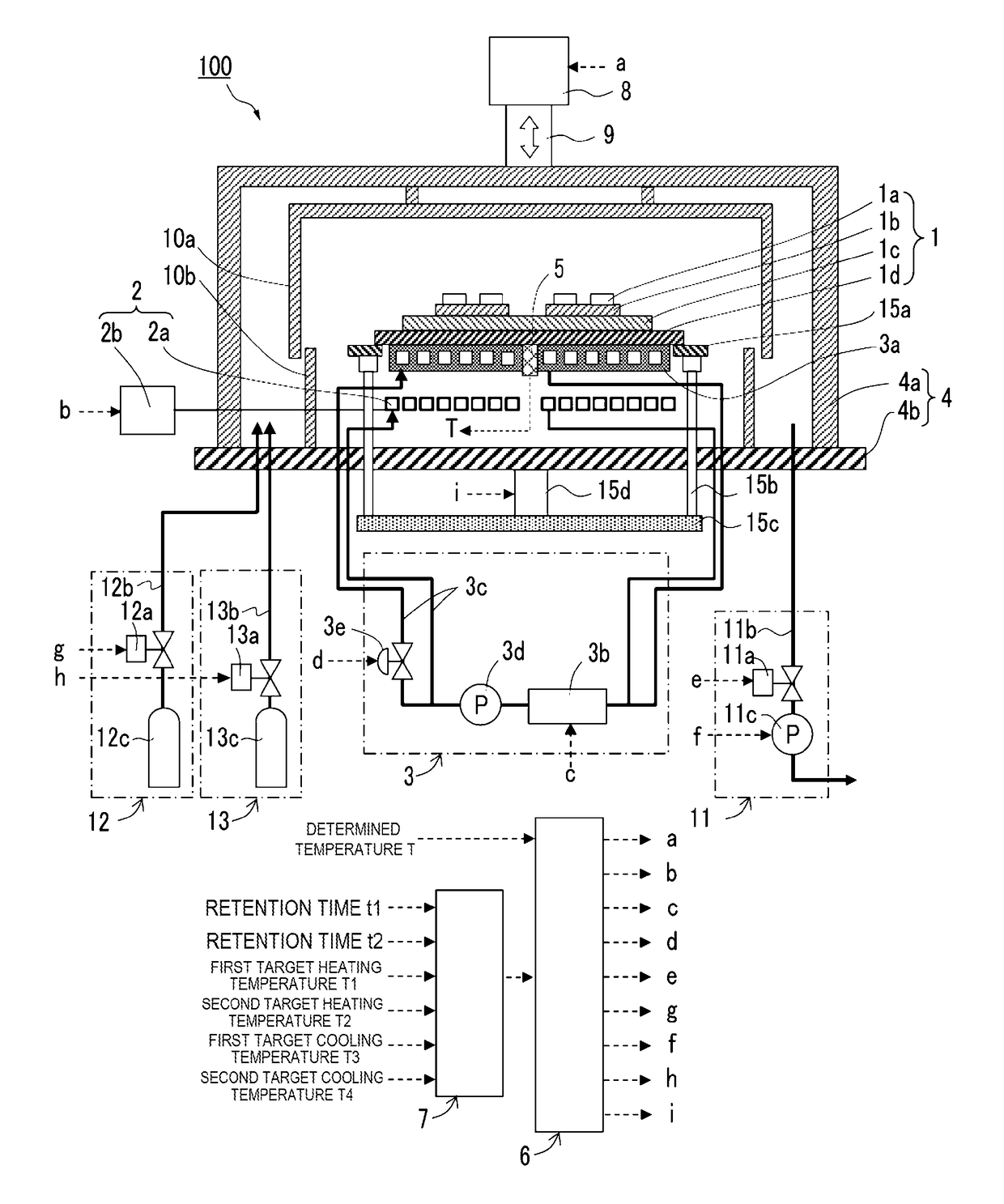
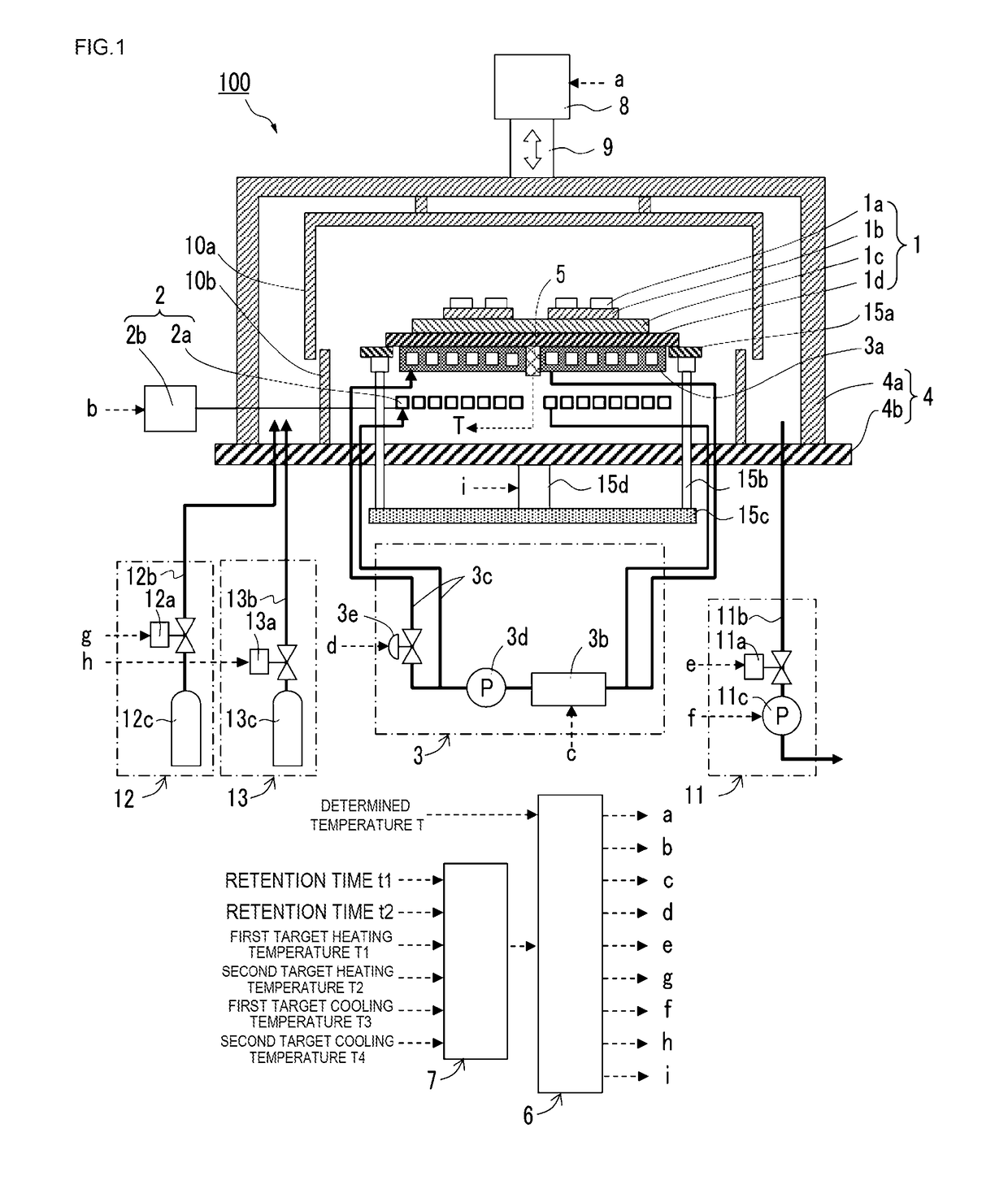
[0055]Hereinafter, referring to FIG. 1, one embodiment of a heating and cooling device of the present disclosure will be described.

[0056]FIG. 1 shows a diagrammatic sketch of a heating and cooling device 100. The heating and cooling device 100 comprises: an airtight processing chamber 4 having an open / close system capable of loading and unloading a member-to-be-processed 1; a cooling unit 3a of a cooling apparatus 3 disposed toward a lower place than the member-to-be-processed 1; an induction heating coil 2a of an induction heating apparatus 2 disposed toward a further lower place than the cooling unit 3a; a transfer apparatus 15 for changing a distance between the member-to-be-processed 1 and the cooling unit 3a; a temperature sensor 5 for determining a temperature of the member-to-be-processed 1; a control apparatus 6 for controlling the induction heating apparatus 2 and the cooling apparatus 3 on the basis of the determined temperature; and an inputting apparatus 7 for inputting ...


PUM

PropertyMeasurementUnit
Temperatureaaaaaaaaaa
Distanceaaaaaaaaaa
Internal pressureaaaaaaaaaa

Abstract

A heating and cooling device including: an airtight processing chamber openable to load a member-to-be-processed in the airtight processing chamber; a transfer apparatus to adjust a distance between the member-to-be-processed and a cooling unit that cools the member-to-be-processed, by moving the member-to-be-processed and/or the cooling unit; an induction heating apparatus to heat the member-to-be-processed, including a induction heating coil; a cooling apparatus to cool the member-to-be-processed by cooling the cooling unit; a temperature sensor to determine a temperature of the member-to-be-processed; and a controller to control the induction heating apparatus and the cooling apparatus based on the temperature determined by the temperature sensor.

Description

CROSS-REFERENCE TO RELATED APPLICATIONS[0001]This application is a continuation application, filed under 35 U.S.C. §111(a), of International Application PCT / JP2015 / 086244 filed on Dec. 25, 2015 and claims foreign priority to Japanese Patent Application No. 2014-265389, filed Dec. 26, 2014 and Japanese Patent Application No. 2014-265376, filed Dec. 26, 2014, the content of each of which is incorporated herein by reference in its entirety.BACKGROUND[0002]1. Field[0003]The present disclosure relates to a heating and cooling device, particularly a heating and cooling device by which a semiconductor element is suitably soldered to a substrate.[0004]2. Related Art[0005]In a conventional soldering apparatus, it is known for a continuous-conveying-type reflow furnace to perform a reflow process, while putting a member for soldering on a conveyer, so as to pass through a preliminary heating zone, a full heating zone, and a cooling zone. Generally, the reflow furnace is configured to open to ...

Claims


Application Information

Patent Timeline
IPC IPC(8): B23K1/002H01L21/67H01L23/00B23K1/008B23K3/047
CPCB23K1/002B23K1/008B23K3/0475H01L24/75H01L21/67248H01L21/67103H01L2224/759B23K2201/40H01L2224/75101H01L2224/7565H01L2224/75501H01L2224/75265H01L21/67144H01L21/67109H01L21/67115B23K3/085H05K3/3494B23K2101/40H01L2224/97H01L2224/83222H01L2224/7598H01L2224/83075H01L2224/751H01L24/83H01L24/97H01L2224/32225H01L2224/291H01L2224/83H01L2924/014B23K31/02H05K3/34
Inventor YOKOYAMA, SHOJIMATSUSHITA, TAKESHINAKAHARA, HIROAKITAKEUCHI, MASAKIWADA, TAKENORIMOMOSE, MASAHIROKIKUCHI, MASAHIROIGARASHI, YOSHIONARUSE, MITSUHIRO
Owner FUJI ELECTRIC CO LTD
Why Eureka
Try Eureka