Spectrum sharing system and method thereof

a spectrum sharing and spectrum technology, applied in the field of wireless communication, can solve the problems of increasing pressure on government and military systems, interference to radars, and difficulty for certain radars to operate in these bands at these locations, so as to improve spectral utilization and efficiency, and efficient spectrum utilization

Inactive Publication Date: 2017-07-20
BAE SYST INFORMATION & ELECTRONICS SYST INTERGRATION INC
View PDF7 Cites 18 Cited by
  • Summary
  • Abstract
  • Description
  • Claims
  • Application Information

AI Technical Summary

Benefits of technology

[0016]The present disclosure will allow military radars to share spectrum with other military and commercial wireless communications systems. In some parts of the world, this will allow military radars to operate in the spectrum that has otherwise been allocated to commercial cellular wireless and satellite services. In other parts of the world, this will result in greater than 400 MHz of additional spectrum to be available for radar and communications dual use. This technique will enable sharing between military and commercial systems for enhanced spectral utilization and efficiency.
[0017]This disclosure relates to the concept of advanced beaconing in the form of an information sharing subsystem (ISS) to enable spectrum sharing between radar and wireless communications systems. This disclosure will enable spectrum sharing between radar and communications systems. In particular, this technique provides a co-existence mechanism by which spectrum sharing information can be provided by the radar to the communications system in a timely and secure fashion to enable efficient spectrum utilization.
[0018]In one aspect, the disclosure provides a spectrum sharing system which includes an advanced beacon (e.g.: a low latency RF link) as part of an information sharing subsystem. The advanced beacon signal carries part or whole of the radar spectrum transmission schedule in an obfuscated way such as not to reveal the geolocation of the radar, but it conveys enough information for the communication systems to determine how to use the spectrum. The information sharing subsystem directs nodes, such as cell phones, to share spectrum based on spectrum sharing instructions contained in the advanced beacon. The spectrum sharing system permits out-of-band sharing of spectrum white space, as well as sharing of in-band spectrum gray space.

Problems solved by technology

This cellular wireless growth has resulted in increasing pressure on government and military systems that have traditionally enjoyed unfettered and unrestricted access to spectrum.
As a result, it has become difficult for certain radars to operate in these bands at these locations to conduct their missions.
However there are known issues with DFS.
If a device is misconfigured, it will not implement DFS correctly, and may cause interference to radars.
Typically there is no “positive control” of the WiFi devices is possible.
In addition, DFS is not very flexible.
There is no way to vary the sharing policy based on current situation, or type of wireless device, etc.
In some cases however, radar operation and signatures cannot be easily shared with the commercial entities.
So while in TV band, it is possible for spectrum to be shared using databases since the TV broadcast equipment does not change the frequency of its operation, it is difficult to have a database enabled spectrum sharing with radars that are used to hop over the entire available frequency band, without constraining the radar operation and hence reducing its performance.
However, that is not optimal use of the spectrum.
The previous spectrum sharing methods wasted spectrum because those methods based their sharing techniques on an inflexible binary approach (e.g.: communications devices are allowed or dis-allowed to use a channel).
Thus, issues continue to exist with the demand for spectrum resources as communication technology advances.
Particularly, spectrum sharing with government and military radars is challenging.
Secondly, in some countries, this spectrum has already been allocated to the commercial cellular operators for their services.
As a result, it is not easy for radars to operate in these bands.

Method used


Image

  • Spectrum sharing system and method thereof
  • Spectrum sharing system and method thereof
  • Spectrum sharing system and method thereof

Examples


Embodiment Construction

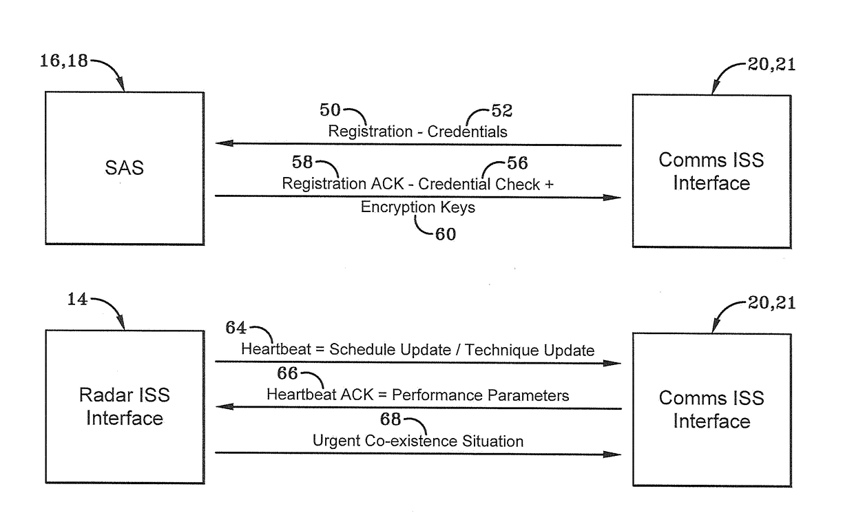
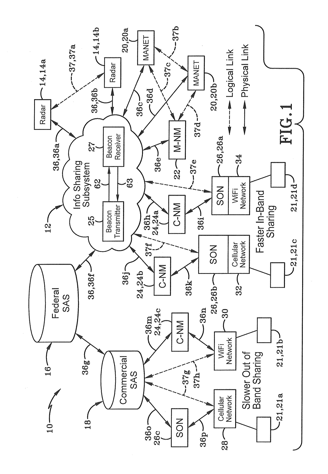
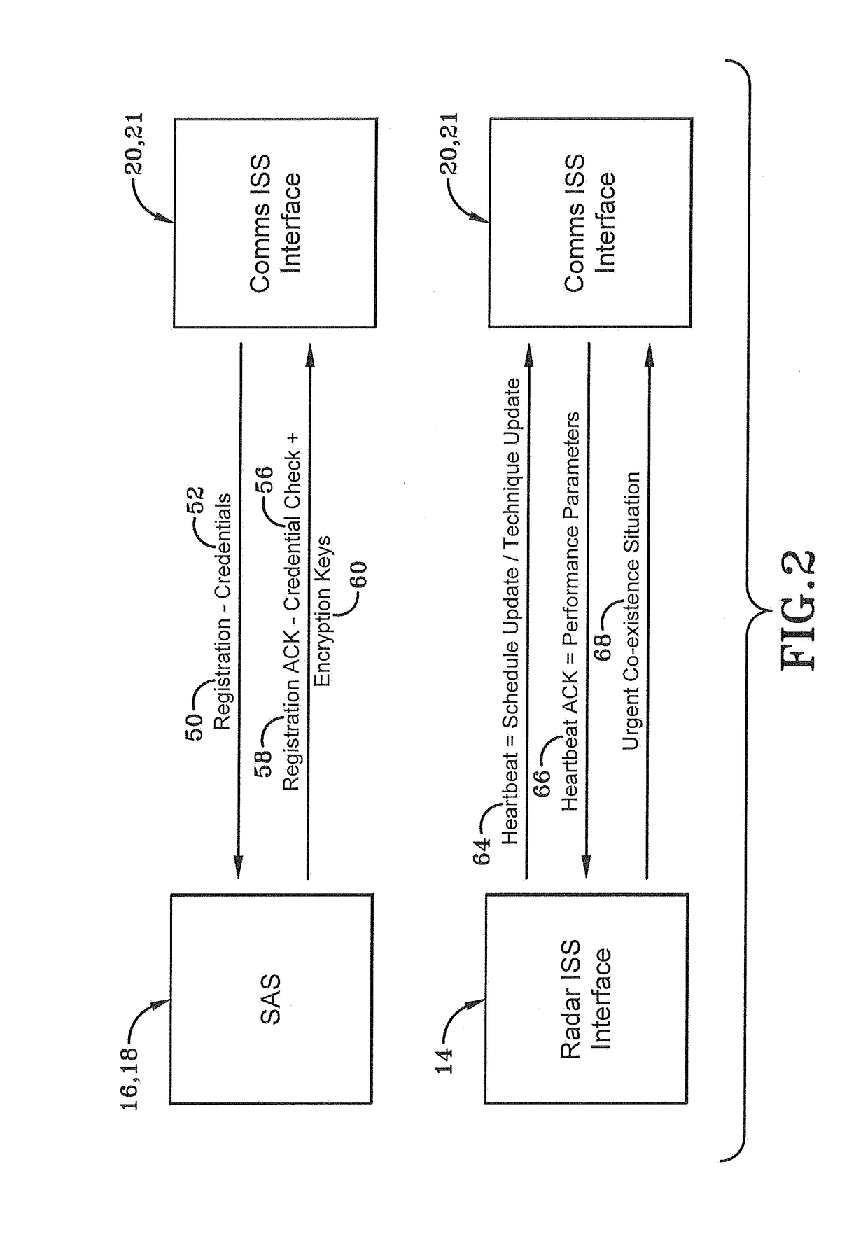
[0037]The present disclosure provides a solution that enables spectrum co-existence between any radar and other communications systems. One exemplary embodiment provides an Information Sharing Subsystem (ISS) that enables government controlled radar and commercial communications systems to exchange operating parameters to share the spectrum. As used herein, government refers to any governmental body in the United States or elsewhere that controls or manages radars, communication systems and spectrum including federal and state agencies and the military, as compared to the commercial entities that manage the same.

[0038]As depicted in FIG. 1, a system for radar and communications spectrum sharing is generally depicted at 10. System 10 may include an ISS 12, one or more radars 14, a government spectrum access system 16, a commercial spectrum access system 18, one or more military Mobile Adhoc Network (MANET) nodes 20, one or more commercial nodes 21 (e.g.: Wi-Fi nodes, cellular base st...


PUM


Abstract

A spectrum sharing system includes an advanced beacon (e.g. a low latency RF link) as part of an information sharing subsystem. The advanced beacon signal carries radar spectrum transmission schedule in an obfuscated way such as not to reveal the geolocation of the radar. The information sharing subsystem directs nodes, such as cell phones, to share spectrum based on spectrum sharing instructions contained in the advanced beacon. The spectrum sharing system permits out-of-band sharing of spectrum white space, as well as sharing of in-band spectrum gray space.

Description

CROSS REFERENCE TO RELATED APPLICATIONS[0001]The present disclosure claims benefit of U.S. provisional application Ser. No. 62 / 132,057 filed on Mar. 12, 2015; the entirety of which is hereby incorporated by reference as if fully rewritten.STATEMENT REGARDING FEDERALLY SPONSORED RESEARCH OR DEVELOPMENT[0002]The U.S. Government has a paid-up license in this invention and the right in limited circumstances to require the patent owner to license others on reasonable terms as provided for by the terms of Contract No. HR0011-13-C-0082 awarded by the Defense Advanced Research Projects Agency.BACKGROUND[0003]Technical Field[0004]The present disclosure relates to wireless communications and more particularly to methods and systems for enabling spectrum sharing between radar and communications systems using advanced beacons and information sharing subsystem.[0005]Background Information[0006]In the United States, the Federal Communications Commission (FCC) defines “Spectrum” as the range of el...

Claims


Application Information

Patent Timeline
Patent Type & Authority Applications(United States)
IPC IPC(8): H04W16/14H04B1/06G01S7/00H04J13/00H04W72/12G01S7/02H04L5/00H04W72/08
CPCH04W16/14H04L5/0051H04B1/06H04W72/082G01S7/003H04L5/0023H04W72/1247G01S7/023H04J13/0062H04K3/226H04L5/003H04L5/0091H04K3/20
Inventor MODY, APURVA N.CARRIGAN, KENNETHCHUANG, JACKLACKPOUR, ALEXSHERMAN, MATTHEW J.ROSENWINKEL, ALAN M.
Owner BAE SYST INFORMATION & ELECTRONICS SYST INTERGRATION INC
Why Eureka
Try Eureka