Ground Level Illumination System

a ground level illumination and robust technology, applied in the direction of instruments, ways, with built-in power, etc., can solve the problems of de facto shallow angle of incidence of any illuminating rays, and difficulty in producing a low f-number optic, so as to reduce the volume of paint required and reduce the electronic power

Inactive Publication Date: 2017-07-27
ROAD STUDS UK LTD
View PDF2 Cites 13 Cited by
  • Summary
  • Abstract
  • Description
  • Claims
  • Application Information

AI Technical Summary

Benefits of technology

nother embodiment the intensity distribution of the illuminating beam is used to illuminate an area of paint or other markings at ground level. The paint can be simply reflective—perhaps enhanced by the addition of reflective particles. Additionally or alternatively, the paint can be luminous (phosphorescent) so that when it has been “charged” by incident light falling onto it from the illumination system or from the sun, it subsequently emits light (not necessarily at the same wavelengths as the incident light) over an extended time period, which may be minutes or hours. The illuminating beam intensity distribution is controlled in such a way that it provides a uniform illumination (when viewed by the pathway user) after reflection from said luminous paint. The painted area illuminated by the beam may take the form of a pattern of spots or strips which are controlled in their density (i.e. number of dots per unit area) such that a desired intensity pattern may be achieved.<b class="d_n
provides shaped illuminated areas having uniform illumination. In the case of luminous re-chargeable paint, the intensity distribution of the illumination is arranged to provide effective charging of the paint and uniform lux values over the whole length of the illuminated area. At night or in cloudy conditions where self-luminous re-chargeable paint would not be charged, a charge would be automatically be provided by the illumination system. In combination with the paint, the overall system would require much lower electronic power because it would only need to top up the “charge” in the paint that could not be provided from sunlight. The area of ground covered by the paint and the volume of paint required would also be minimised. In practical implementation of the pattern of strips or dot a thin mask template would be used to enable paint to adhere to only where it is required and to block paint from reaching the blank areas in between the strips.<b class="d_n

Problems solved by technology

Firstly the angle of incidence of any illuminating rays are de facto shallow, i.e. at extremely oblique angles.
Producing a low f-number optic (including non-imaging concentrator optics which may be characterised as having an equivalent to an f-number) is technically challenging.
These arguments indicate that having a collimating lens entirely above ground level for the purpose of ground level illumination results in a relatively high, large optic which is disadvantageous.
In addition, the requirement for robustness means that discrete optics which have an air space between them or between the source and the optic are potential points of mechanical weakness.
Because of the finite size of the source, particularly one such as a high lumen power LED source, the real rays will be much more complicated and include many spurious rays.
However, for practical purposes we must assume the refracted beam will not be perfectly collimated.
The limitations of Coddington theory apply, restricting the divergence angles to a few degrees.

Method used


Image

  • Ground Level Illumination System
  • Ground Level Illumination System
  • Ground Level Illumination System

Examples


Embodiment Construction

[0091]The invention will now be described in detail with the aid of the accompanying drawings.

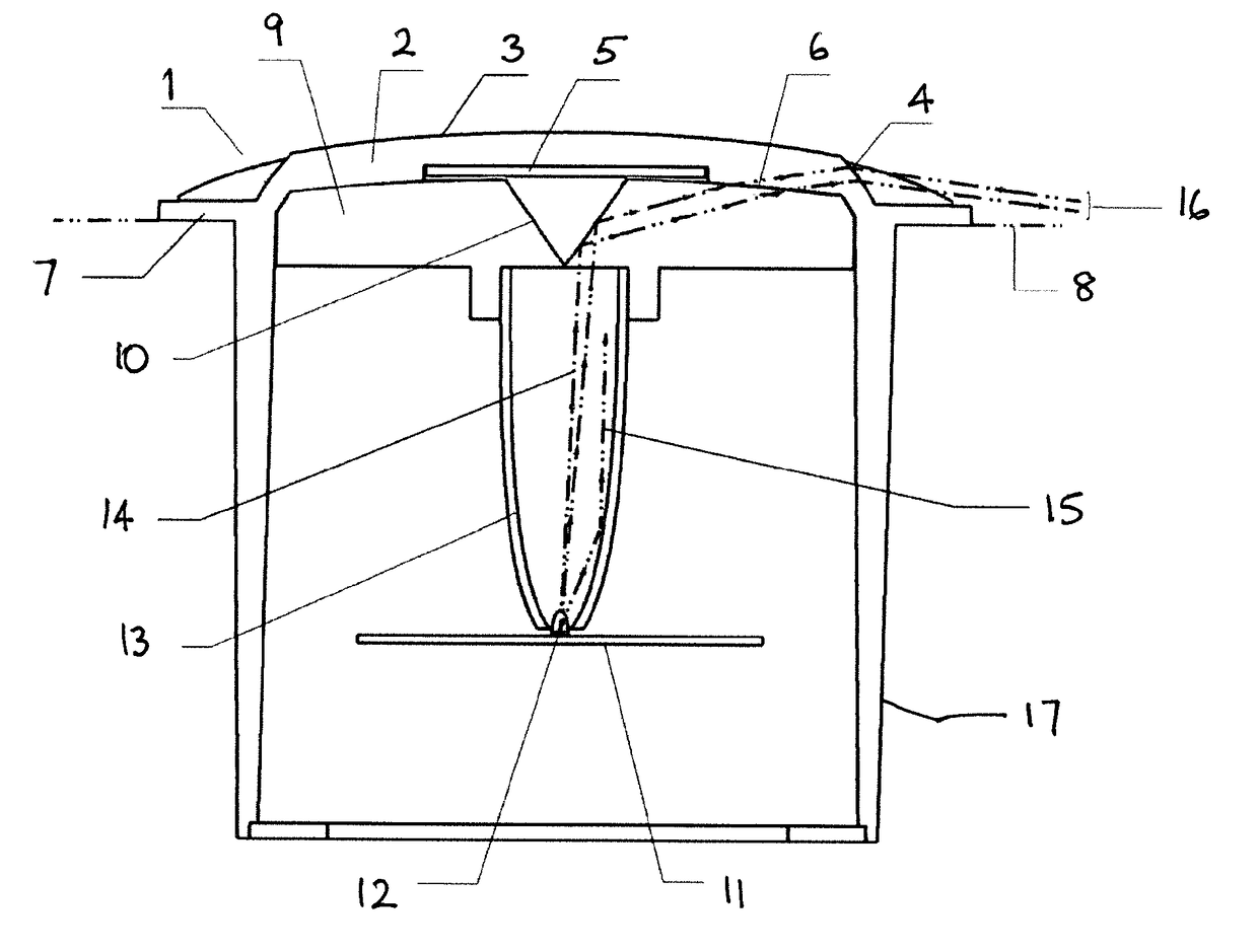
[0092]FIG. 1 shows a cross-sectional side view of a ground level illumination system 1, such as could be used to illuminate a road or pathway. For clarity only the key aspects of the illumination in one direction are described in detail. However, the arrangement is symmetrical and provides bi-directional illumination to the left and right sides as viewed in the drawing. A top block 2 comprising a low refractive index material has a curved upper surface 3. The refractive index of the top optical block 2 is 1.5 or less. The top block 2 incorporates a toroidal refractive surface 4 and a pocket to accommodate a solar cell 5. The upper surface 3 provides optical gain and helps the collection of sunlight energy for the solar cell 5. The top block 2 has a lower curved surface 6 and has a flange 7 which sits at the ground level as indicated by construction line 8.

[0093]The solar cell 5 is used to s...


PUM


Abstract

A ground level illumination system such as a road stud comprises a light source (12) positioned below ground level (8). An optics block (9) and a top block (2) transmit light from the source (12) to the exterior, the light rising at a shallow angle as a collimated beam in the top block (2) to emerge at a window (4) above the ground level (8). The window (4) is shaped to refract the light into a beam (16) that descends at a shallow angle relative to the ground level (8). The emerging beam (16) may be used to illuminate road markings (26) formed from luminous paint that can be re-charged by the illumination system. A feedback mechanism (82) can measure reflected light levels to maintain the optimal “charge” in the paint. A further element (84) of the system may also compare the intensity of reflected light at different wavelengths to detect the presence of fog.

Description

FIELD OF THE INVENTION[0001]The present invention relates to a compact and robust ground level illumination system such as a road stud that provides well defined illumination for a substantially horizontal receiving plane. The divergence of the illuminating rays in the vertical direction is controlled such that the light is incident on a pre-defined area on the ground plane. When the system is employed at night or in low light level conditions on a pathway it provides additional safety to the user of the pathway. The system can thus be beneficially employed on pathways used by pedestrians, cyclists and vehicles, especially road vehicles. The system may also be employed to illuminate aircraft runways.BACKGROUND[0002]Authorities, planners and designers are concerned with providing safer systems for transport with an aim to avoiding injury and death of road users.[0003]For example there is great concern with reducing the numbers of accidents that occur on roads. Legislators are constan...

Claims


Application Information

Patent Timeline
Patent Type & Authority Applications(United States)
IPC IPC(8): E01F9/559F21S9/02B64F1/20F21V5/02F21V7/04G02B27/30F21S8/02
CPCE01F9/559G02B27/30F21S9/02F21S8/022F21V5/02F21V7/04B64F1/205B64D2203/00
Inventor MESSIOU, ANTOINE YVONBARKER, THOMAS JAMES
Owner ROAD STUDS UK LTD
Why Eureka
Try Eureka