Electrolyte System For Rechargeable Flow Battery

a flow battery and electrolyte technology, applied in the direction of electrolyte fuel cells, fuel cells, aqueous electrolyte fuel cells, etc., can solve the problems of increasing the cost of electrolyte pumping, increasing the cost, and difficult to maintain stable electrolyte levels, so as to facilitate the manufacturing and field maintenance service of the battery, and improve the performance. stability

Inactive Publication Date: 2017-07-27
FAITH TECH INC
View PDF4 Cites 7 Cited by
  • Summary
  • Abstract
  • Description
  • Claims
  • Application Information

AI Technical Summary

Benefits of technology

[0013]Therefore, according to one aspect of an exemplary embodiment of the invention, an Unproved electrolyte system is provided for better and stable performance of a zinc-bromine flow battery with an ion-exchange membrane placed between the anolyte and the catholyte. The catholyte and anolyte are formed of a symmetric electrolyte, such that the anolyte and catholyte have identical compositions, which results in minimal electrolyte drifting from catholyte to anolyte. In addition, the use of identical main compounds for both anolyte and catholyte eases the manufacturing and field maintenance service of the battery.

Problems solved by technology

Electrolyte pumping power consumption will also increase due to higher electrolyte density and viscosity at a higher ZnBr2 concentration.
Chemical material, cost is also consequently increased.
However, in analyzing the operation of these batteries, it was determined that stable electrolyte levels were very hard to maintain due to different electrolyte properties such as density, viscosity, and concentration, between the catholyte and the anolyte.
This resulted in fast cell performance decay and eventually premature failure of the battery.
In addition to these issues, the prior art zinc-bromine flow batteries had far lower energy efficiency than commercial Li-ion battery.
The low battery voltage efficiency (VE %) or high battery resistance with electrolytes of this type is partially due to low electrolyte conductivity.
Further, the prior art catholyte largely drifted into the anolyte side with repeated electrolyte composition changes during charge-discharge cycles of these prior art batteries.

Method used


Image

  • Electrolyte System For Rechargeable Flow Battery
  • Electrolyte System For Rechargeable Flow Battery
  • Electrolyte System For Rechargeable Flow Battery

Examples


Embodiment Construction

[0029]In exemplary embodiments of the invention, an improved electrolyte system for use in an electrolyte flow battery, as are known in the art, is provided.

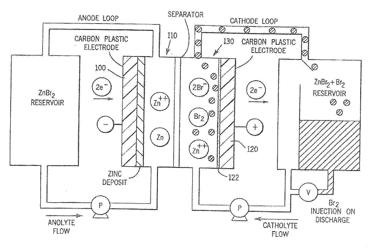
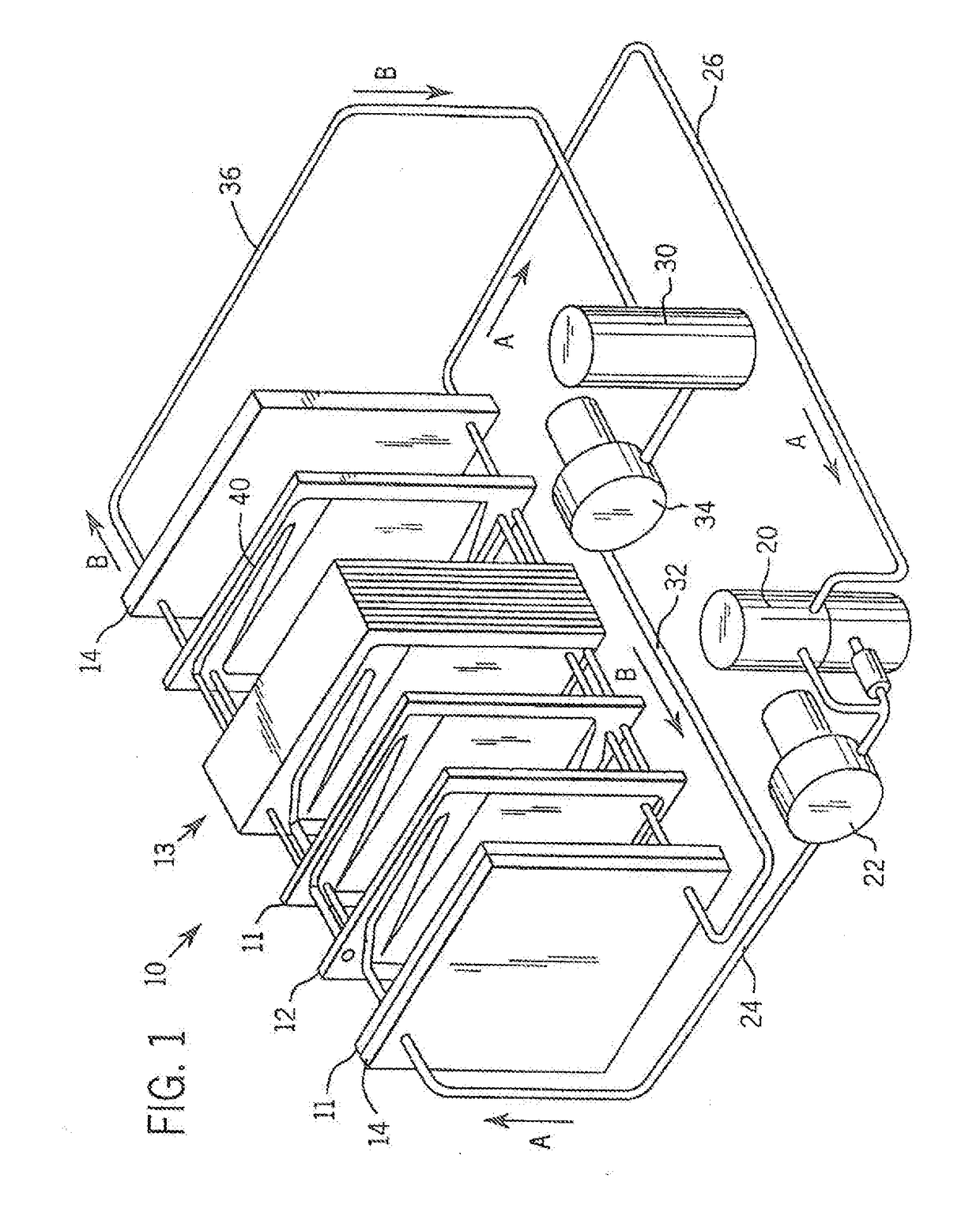
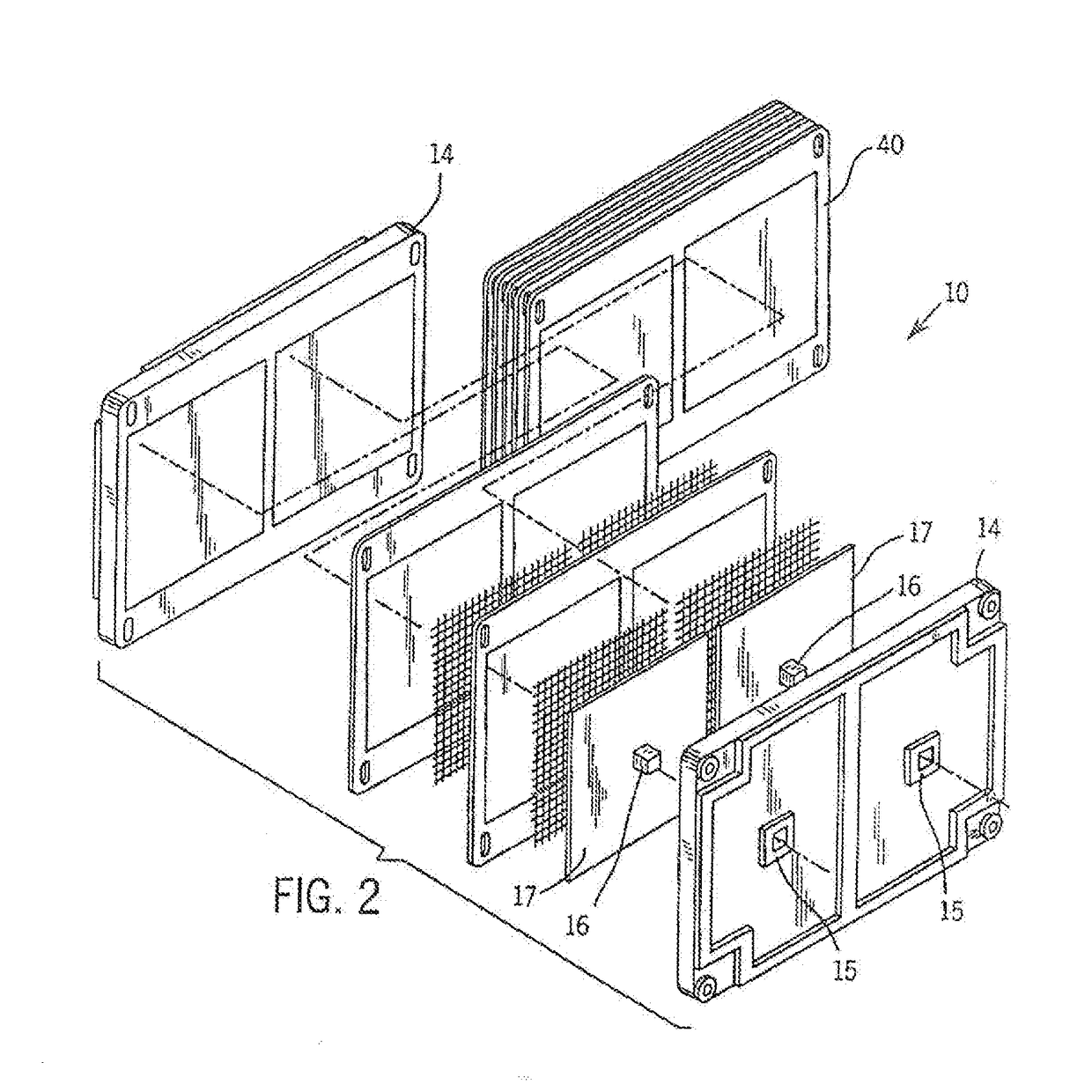
[0030]Referring more particularly to the drawings, one particular exemplary embodiment of an electrolyte flow battery including zinc complexes, as are known in the art, such as U.S. Pat. Nos. 4,049,886; 5,002,841; 5,188,915 and 5,650,239, and US Patent Application Publication No. 2012 / 0326672, each of which is expressly incorporated by reference herein for all purposes in its entirety, and which each disclose a zinc-bromine battery. is shown in an exploded view and is designated generally by the numeral 10 in FIG. 1. The zinc-bromine battery 10 includes a series of electrodes 11 and separators 12, welded together to form a stack 13 of electrochemical cells. Each battery 10 includes a predetermined number of electrodes 11 and separators 12 and. thus, a predetermined number of electrochemical cells. As best seen in FIG. 2, respect...


PUM

PropertyMeasurementUnit
coulombic efficiencyaaaaaaaaaa
limiting charge voltageaaaaaaaaaa
conductivityaaaaaaaaaa

Abstract

An electrolyte system is provided for a rechargeable electrode zinc-halogen flow battery that utilizes a highly similar or identical electrolyte positioned on both sides of an ion-conducting membrane. The electrolyte system containing zinc salts, electrolyte conductivity enhancer, and an appropriate amount of bromine complexing agent achieves significant improvements on battery energy efficiency, self-discharge rate, and electrolyte level cycle stability over the prior art electrolyte systems.

Description

CROSS-REFERENCE TO RELATED APPLICATIONS[0001]This application claims priority from U.S. Provisional Patent Application Ser. No. 62 / 287,524, filed on Jan. 27, 2016, the entirety of which is expressly incorporated by reference herein for all purposes.FIELD OF THE INVENTION[0002]The present invention relates generally to rechargeable flow batteries, and more specifically to the charge-carrying compounds utilized in zinc-halogen batteriesBACKGROUND OF THE INVENTION[0003]Rechargeable flow batteries, including, for example, those disclosed in US Patent Application Publication No. US2012 / 0326672 entitled Reversible Polarity Operation And Switching Method For ZnBr Flow Battery When Connected To Common DC Bus, and U.S. Pat. Nos. 4,049,886: 5,002,841; 5,188,915 and 5,650,239, each of which is expressly incorporated by reference herein for all purposes in its entirety, utilize electrolytes incorporating metal ion redox couples / compounds, including but not limited to vanadium, zinc-halogen, and...

Claims


Application Information

Patent Timeline
Patent Type & Authority Applications(United States)
IPC IPC(8): H01M8/18H01M8/08
CPCH01M8/188H01M2300/0002H01M8/08H01M10/365H01M12/085Y02E60/10Y02E60/50
Inventor LEX, PETERBI, WU
Owner FAITH TECH INC
Why Eureka
Try Eureka