Exhaust heat recovery and hydrocarbon trapping

a technology of exhaust heat recovery and hydrocarbon trapping, which is applied in the direction of exhaust treatment electric control, electrical control, machines/engines, etc., can solve the problems of reducing the hc storing function of zeolite, degrading the exhaust emissions, and not being able to effectively convert cold-start exhaust hydrocarbons, etc., to improve engine efficiency, improve fuel economy, and warm the passenger cabin quickly

Inactive Publication Date: 2017-08-03
FORD GLOBAL TECH LLC
View PDF7 Cites 8 Cited by
  • Summary
  • Abstract
  • Description
  • Claims
  • Application Information

AI Technical Summary

Benefits of technology

[0002]Engines may be configured with an exhaust heat recovery system for recovering heat from an internal combustion engines exhaust energy. The heat is transferred from the hot exhaust gas to a coolant through an exhaust gas heat exchanger system. The heat from the coolant, circulated through the heater core, may be utilized for func

Problems solved by technology

Due to low temperature, catalysts may not be able to effectively convert cold-start exhaust hydrocarbons.
However, the inventors herein have recognized the above issues and potential disadvantages with the above approach.
As one example, due to the position of the HC trap, exhaust entering the trap may not be cold enough for substantially all cold-start hydrocarbons to be adsorbed, leading to degraded exhaust emissions.
In addition, water from the cold exhaust may condense on th

Method used


Image

  • Exhaust heat recovery and hydrocarbon trapping
  • Exhaust heat recovery and hydrocarbon trapping
  • Exhaust heat recovery and hydrocarbon trapping

Examples


Embodiment Construction

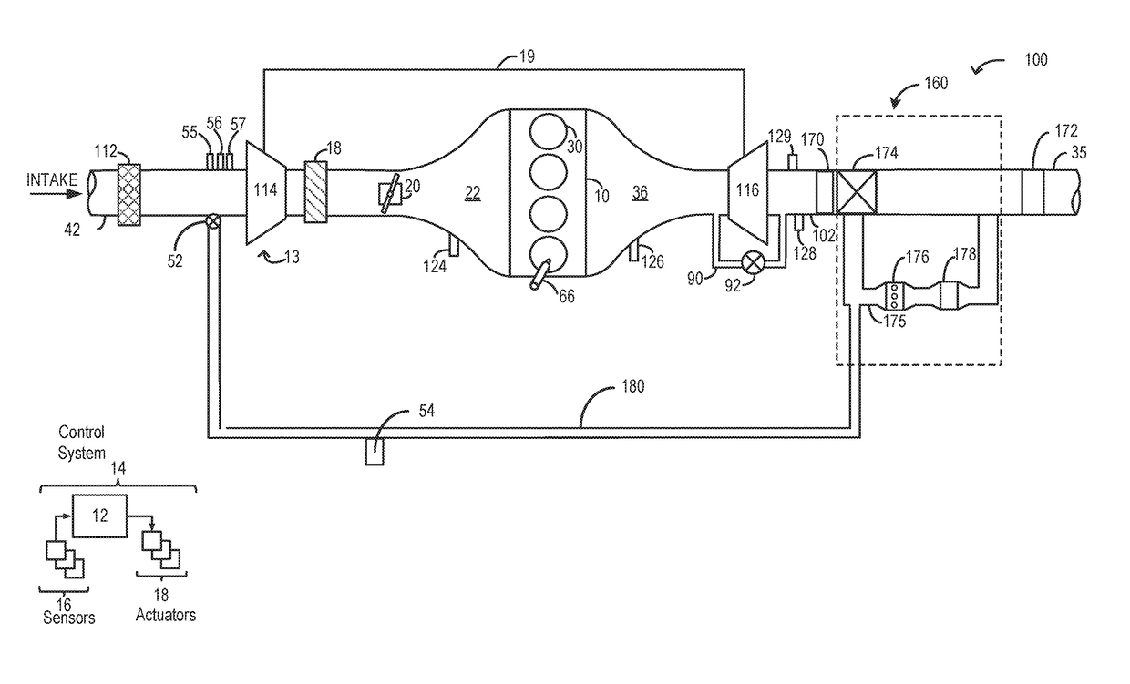
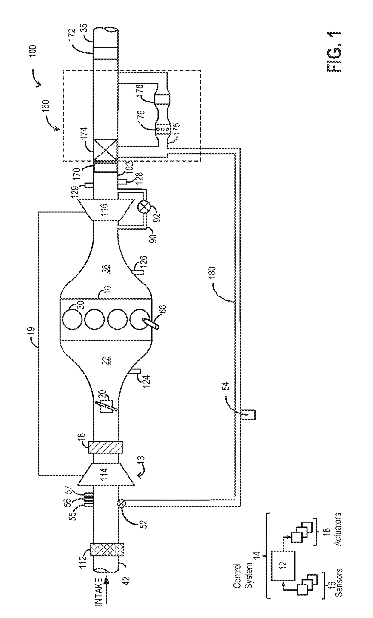
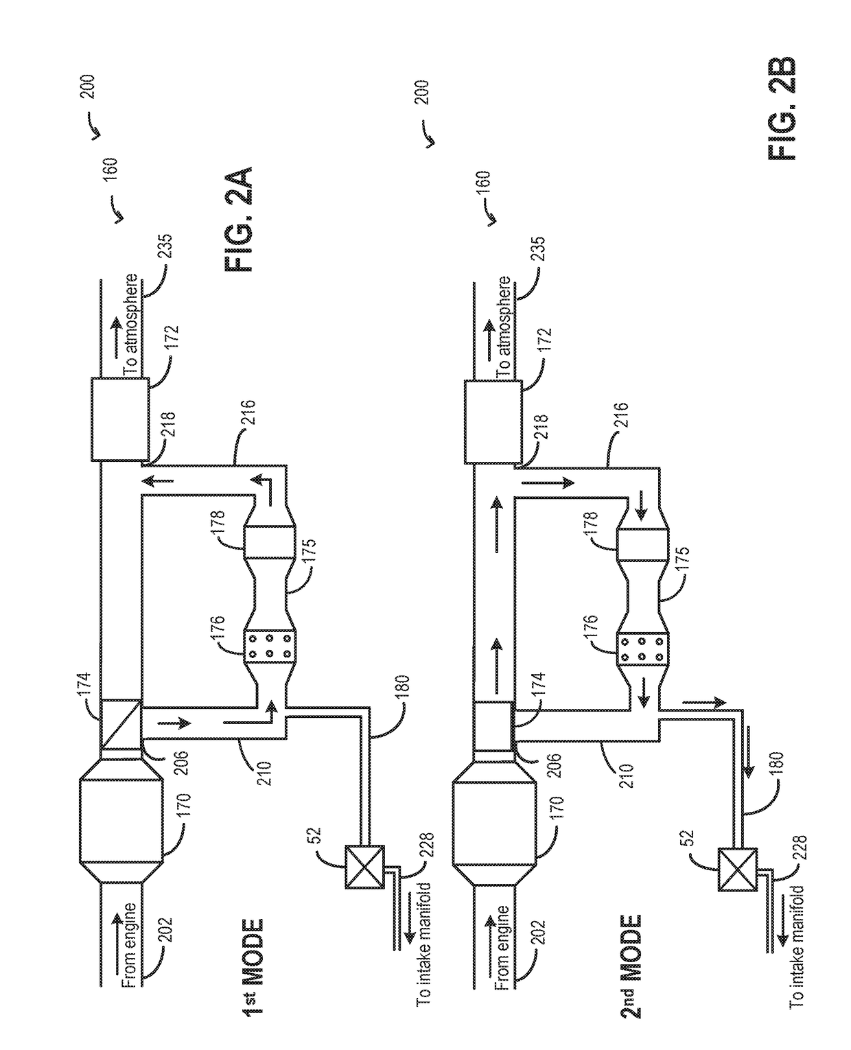
[0017]The following description relates to systems and methods for improving exhaust heat recovery using a single heat exchanger and hydrocarbon trap at an exhaust bypass assembly. An example engine system comprising an exhaust bypass assembly with a heat exchanger and a HC trap is shown in FIG. 1. A diverter valve is used to enable bidirectional flow of exhaust through the heat exchanger and the HC trap in the bypass assembly of FIG. 1. Two example modes of operation of the system of FIG. 1 are elaborated with reference to FIGS. 2A-2B, and 4. An engine controller may be configured to perform a control routine, such as the example routine of FIG. 3, to vary the position of the diverter valve in order to operate the exhaust bypass assembly in one of the plurality of example modes with exhaust flow through the heat exchanger and HC trap adjusted. Example operations of the exhaust bypass assembly are shown with reference to FIG. 5.

[0018]FIG. 1 schematically shows aspects of an example ...


PUM


Abstract

Methods and systems are provided for exhaust heat recovery and hydrocarbon trapping at an exhaust bypass assembly. Exhaust gas may flow in both directions through an exhaust bypass passage and each of a HC trap and a heat exchanger coupled to the bypass passage. The HC trap may be purged with the hot exhaust and heat from the exhaust may be recovered at the heat exchanger.

Description

FIELD[0001]The present description relates generally to methods and systems for exhaust heat recovery and hydrocarbon trapping at an exhaust bypass assembly.BACKGROUND / SUMMARY[0002]Engines may be configured with an exhaust heat recovery system for recovering heat from an internal combustion engines exhaust energy. The heat is transferred from the hot exhaust gas to a coolant through an exhaust gas heat exchanger system. The heat from the coolant, circulated through the heater core, may be utilized for functions such as heating the cylinder head thus warming the passenger cabin quickly, thereby improving engine efficiency. In hybrid electric vehicles, the recovery of exhaust heat improves fuel economy by warming engine temperatures quicker, thereby allowing for a faster engine shut-off and extended use of the vehicle in an electric mode.[0003]Exhaust heat may also be retrieved at an exhaust gas recirculation (EGR) cooler. An EGR cooler may be coupled to an EGR delivery system to brin...

Claims


Application Information

Patent Timeline
IPC IPC(8): F01N9/00F02M26/35F02M26/22F01N3/08F02M26/15
CPCF01N9/00F01N3/0835F02M26/15F02M2026/004F02M26/35F01N2570/12F01N2390/00F02M26/22B60H1/18F01N3/035F01N3/0821F01N3/0878F01N5/02F01N2240/02F01N2370/24F02D41/0047F01N2410/03Y02T10/12Y02T10/40
Inventor UHRICH, MICHAEL JAMESULREY, JOSEPH NORMANCAVATAIO, GIOVANNIBANKER, ADAM NATHAN
Owner FORD GLOBAL TECH LLC
Why Eureka
Try Eureka