Method for the non-destructive testing of a test object by means of ultrasound and device therefor

a test object and non-destructive technology, applied in the direction of instruments, measurement devices, analysing solids using sonic/ultrasonic/infrasonic waves, etc., can solve problems such as faulty echo indications, and achieve the effect of increasing testing speeds

Active Publication Date: 2017-08-03
GE SENSING & INSPECTION TECH GMBH
View PDF3 Cites 55 Cited by
  • Summary
  • Abstract
  • Description
  • Claims
  • Application Information

AI Technical Summary

Benefits of technology

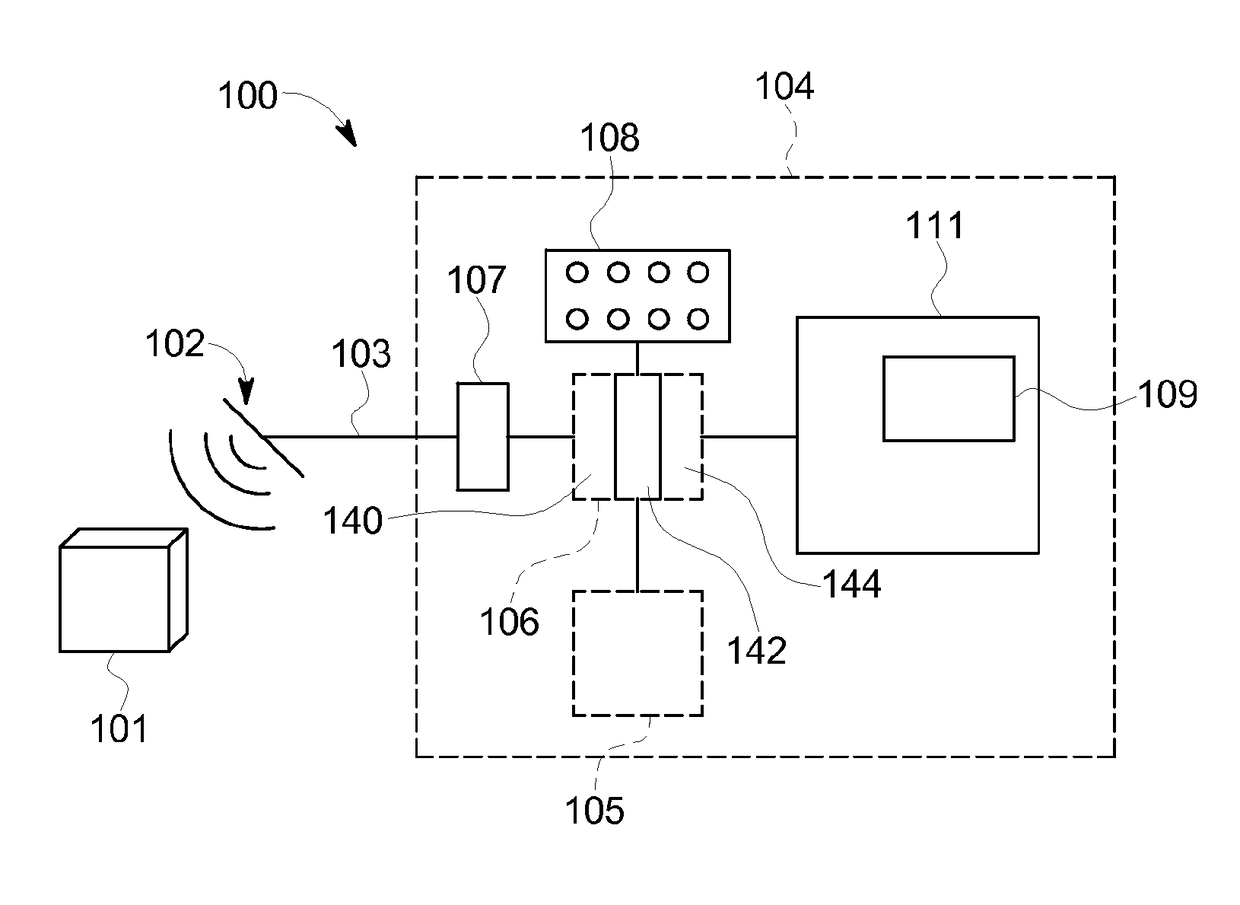
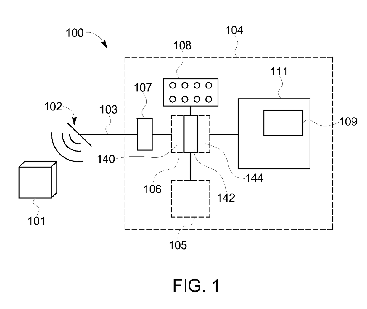
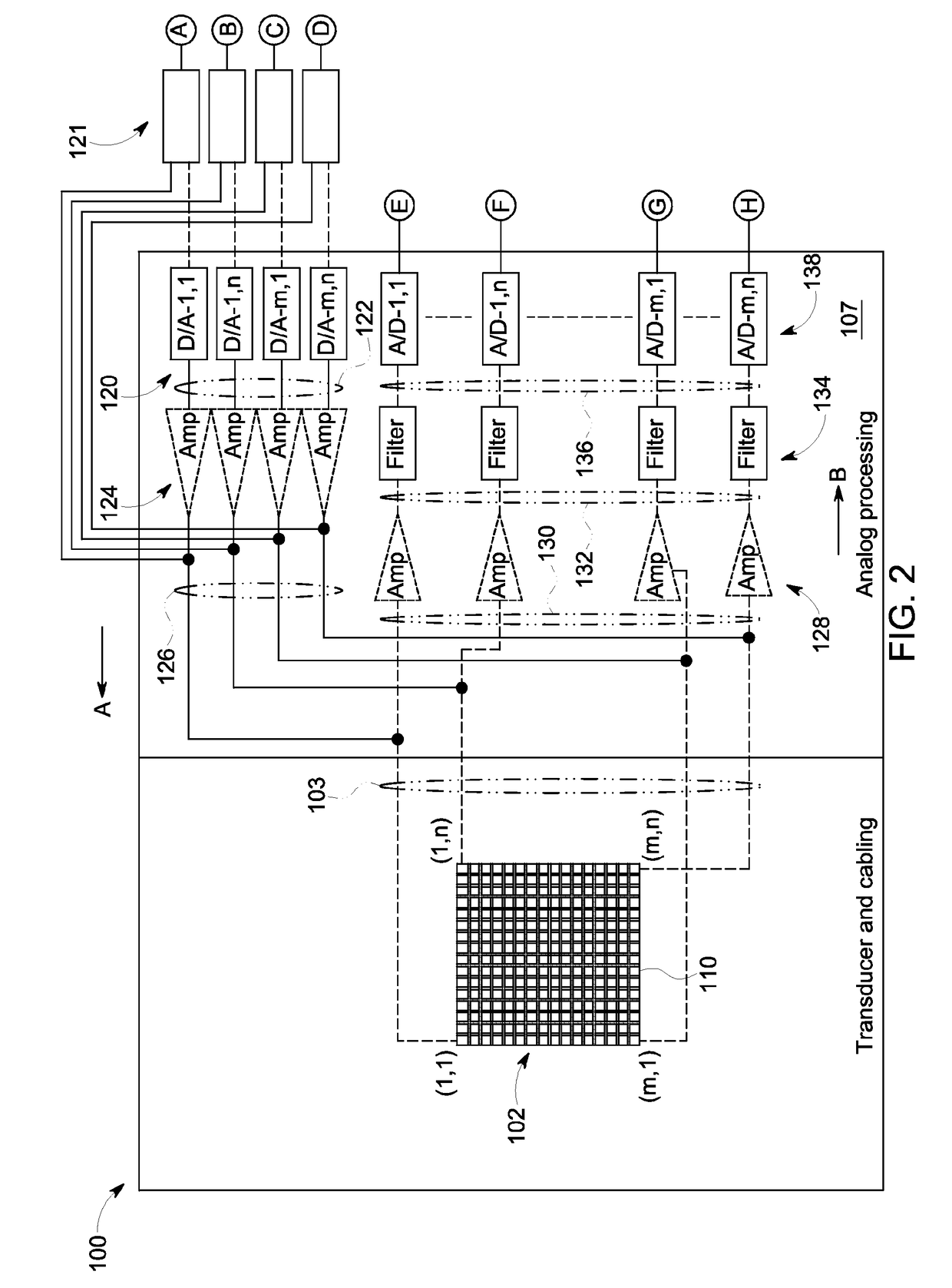
[0007]The method according to the embodiments is based on a development of the methods known from the prior art, which are based on the insonification of a directed plane wave into the test object, in that, using suitable beam generation techniques by means of an array of individually drivable ultrasonic transmitting transducers, a tested ultrasonic field, which is adapted in its geometry to the geometry of the test object and to the testing task to be carried out, can be specifically insonified into the test object. This means that the methods known from the prior art are being developed as regards transmission, with techniques being used in this case that have become known under the name “ultrasonic holography”. They are based on the insight that it is possible to predefine, at any point in the test object volume, an ultrasonic field with a desired ultrasonic field geometry, and to reckon back from this ultrasonic field geometry the ultrasonic field distribution in time and space at the location of an array of ultrasonic transmitting transducers. If the array of ultrasonic transmitting transducers emits this distribution in time and space of ultrasonic signals into the test object, then the predefined ultrasonic field distribution desired at the observed point in the test object volume results therefrom. It is thus possible to specifically generate field distributions of the ultrasonic field insonified into the test object, which are optimally suitable for the transsonification of the volume regions of the test object to be examined. In addition, multiple echoes and crosstalk between different regions of the insonified ultrasonic field can be suppressed by skilled selection of the field geometry.
[0008]Therefore, the method according to the embodiments permits the insonification large sectors of the test object with a single ultrasonic pulse so effectively that echo signals can be received from them in principle. Therefore, fewer ultrasonic pulses are required than in the methods known from the prior art in order to transsonify the entire test object volume to be examined. For this reason, significantly increased testing speeds can be realized with the method according to the embodiments and the testing device according to the embodiments.

Problems solved by technology

Though the aforementioned methods have proved their worth in the practice of largely automated material inspection, it was found, nevertheless, that difficulties related to multiple echoes can arise which may possibly result in faulty echo indications, particularly in the case of complex geometries.

Method used


Image

  • Method for the non-destructive testing of a test object by means of ultrasound and device therefor
  • Method for the non-destructive testing of a test object by means of ultrasound and device therefor
  • Method for the non-destructive testing of a test object by means of ultrasound and device therefor

Examples


Embodiment Construction

[0071]Certain exemplary embodiments will now be described to provide an overall understanding of the principles of the structure, function, manufacture, and use of the devices, systems, and methods disclosed herein. One or more examples of these embodiments are illustrated in the accompanying drawings. Those skilled in the art will understand that the devices, systems, and methods specifically described herein and illustrated in the accompanying drawings are non-limiting exemplary embodiments and that the scope of the present disclosure is defined solely by the claims. The features illustrated or described in connection with one exemplary embodiment may be combined with the features of other embodiments. Such modifications and variations are intended to be included within the scope of the present disclosure.

[0072]Ultrasonic holography imaging systems that use analog excitation signals are capable of producing detailed sound fields that are not constrained by the configuration of the...


PUM

PropertyMeasurementUnit
frequencyaaaaaaaaaa
frequencyaaaaaaaaaa
frequencyaaaaaaaaaa

Abstract

A method for the nondestructive testing of a test object by ultrasound is provided, the method including generating a pulsed ultrasonic field in the test object by means of an array of individually drivable ultrasonic transmitting transducers acoustically coupled to the test object. The ultrasonic transmitting transducers are each driven with a specific analog transient excitation signal, wherein each analog transient excitation signal is generated based on an ultrasonic transmitting transducer-specific stored digital transient excitation function. The method further includes receiving resulting echo signals from the test object by means of an array of individually drivable ultrasonic receiving transducers, with each ultrasonic receiving transducer providing an analog time-resolved echo signal, temporarily storing the time-resolved, transducer-specific, digitized echo signals in the form of an echo signal set, and applying a plurality of different reception processing rules to the echo signal set.

Description

BACKGROUND[0001]The present embodiments relate to a method for the non-destructive testing of a test object by means of ultrasound, particularly to a method for generating a B-scan, C-scan or sector scan or a volume image of a test object. In particular, the test object may be a workpiece or a tool, such as a pipe section, a rod-shaped or plate-shaped material or a pressure vessel, such as a reactor pressure vessel. Further, the subject matter of the present disclosure is a device for carrying out the method according to the present embodiments.[0002]A variety of devices and methods for the non-destructive testing of the volume of a test object by means of ultrasound are known according to the prior art. In particular since the introduction of the so-called phased array technique, which is based on the use of a plurality of independently drivable ultrasonic transducers and which permits a specific control of the insonification angle and the focus position of the generated ultrasonic...

Claims


Application Information

Patent Timeline
Patent Type & Authority Applications(United States)
IPC IPC(8): G01N29/44G01N29/46G01N29/04
CPCG01N29/4454G01N29/04G01N2291/044G01N2291/105G01N29/46G01N29/0645G01N29/262G01N29/343
Inventor KOCH, ROMAN HEINRICHFALTER, STEPHANPRAUSE, REINHARDBREIDENBACH, HELMUTBREIDENBACH, CHRISTOFWEISE, THOMAS
Owner GE SENSING & INSPECTION TECH GMBH
Why Eureka
Try Eureka