Wireless communication system and method for trains and other vehicles using trackside base stations

a technology for wireless communication and trains, which is applied in the direction of climate sustainability, sustainable buildings, high-level techniques, etc., can solve the problems of introducing several potential sources of communication performance degradation, difficult to obtain direct communication between terminal antennas within the carriage and externally located antennas, and difficult to achieve such communication for mobile devices which are moving

Active Publication Date: 2017-08-03
ECOMELA
View PDF0 Cites 11 Cited by
  • Summary
  • Abstract
  • Description
  • Claims
  • Application Information

AI Technical Summary

Benefits of technology

[0010]It is therefore an object of the present invention to provide a method for wireless communication and a wireless communication system for moving vehicles, and in particular a train, which alleviates all or at least some of the above-discussed drawbacks of the presently known systems.
[0020]By switching between a low power mode, which may be used as a default, and a high power mode for the trackside base stations, it becomes possible to “activate” only the base stations in the vicinity of the vehicle with the mobile router, whereas other base stations, farther away, and with which the mobile router would anyway not be able to communicate efficiently, may be set in a low power mode. Hereby, the communication efficiency is improved, since interference between the base stations is reduced. Further, the operation becomes much more cost-effective, since the power is now allocated and used only where it is needed, providing substantial savings in the overall power used.
[0025]The new solution provides better performance than previously known WLAN solutions when used on trains and other vehicles. By means of the present invention, efficient WLAN communication is provided when the access points are provided more than 1 km apart along the vehicle path of travel (such as the train rail), and even when more than 5 km apart, and more than 10 km apart, and more than 20 km apart. Preferably, the access points are arranged with a separating distance in the range 1-20 km, and more preferably in the range 2-20 km, and most preferably in the range 5-20 km, such as 10-20 km.
[0033]The low power mode is preferably set to such a power that communication with mobile routers is still possible, at least at close range. The low power mode may be set to zero, and this would optimize the savings in respect of used power. However, it is preferred to use a low power slightly above zero in the low power mode, so that mobile routers may achieve communication access to the trackside base stations when in the low power mode at least at a close range. Hereby, mobile routers which have lost communication with the system, for example due to lost tracking in the controller, may resume the communication again. For example, the loss of GNSS / GPS signals in the mobile router may in some instances lead to situations where the mobile router is “lost” by the controller, so that no trackside base stations are set in high power mode when the vehicle approaches. However, by ensuring that some communication is possible also in the low power mode, the mobile router will again be detected at least when it passes the next trackside base station, and the communication method as discussed above can then be resumed.
[0035]However, by means of the present invention, the coverage areas of the trackside base stations are preferably arranged with a relatively large overlap area. Preferably, the coverage areas are provided such that the mobile routers will at most time have access to at least two trackside base stations—one ahead of the vehicle and one behind the vehicle. This can be used to enable simultaneous communication with more than one trackside base stations. Thus, the mobile router can preferably be arranged to simultaneously communicate with the external mobile network through at least two trackside base stations when more than one trackside base stations is accessible for the mobile router, thereby providing two concurrently useable data links. This enhances the communication performance significantly, and also alleviates the problems related to handovers.
[0040]The communication can be automatically optimized based on the evaluation, and also optionally on other conditions, such as price, speed, latency, etc. Thus, in addition to the evaluation, prioritizing and assignments may be made based on other static or dynamic parameters, such as signal strength and the like. Such further optimizations are per se known from EP 1 175 757 and WO 15 / 169917 by the same applicant, said documents hereby being incorporated by reference. An automatic selection is then made among the available data links to use the most efficient combination. Hence, a seamless distribution of the data among the different data links is obtained.

Problems solved by technology

It is particularly challenging to achieve such communication for mobile devices which are moving, e.g. when moving over large distances with poor network coverage or when affected by unknown sources of noise interrupting a signal for communication, such as clients moving on e.g. trains, airplanes, and other types of moving vehicles.
Accordingly, train carriages are shielded compartments, and direct communication between terminal antennas within the carriages and externally located antennas is difficult to obtain.
The mobile nature of a client with respect to the base stations may also introduce several potential sources of communication performance degradation.
Such sources may derive from complex terrain, competition for available channels, or the source may be an unknown source of noise related to e.g. radio-frequency interference.
Further, with the new smartphones, and the way these are used, with e.g. continuously operating applications, many phones are active at all times, meaning that many handovers are required when the train moves.
Even though this problem is common for all moving vehicles, it is especially pronounced for vehicles moving at high speed, such as trains and airplanes, and trains are in addition facing problems with poor line-of-sight between the base stations and the train.
This puts a strain on the wireless network infrastructure, leading to poor performance.
However, this solution may still be insufficient to obtain an optimal transmission performance, especially for large data volumes.
Trains and other moving vehicles often pass through areas with bad radio coverage, and present solutions are often unable to handle the required traffic.
However, it has been found that communication via trackside base stations performs very poorly for many communication standards, such as for WLAN standards.
In particular, high power is often needed to obtain adequate communication performance, and also a large number of trackside base stations.
Thus, such trackside communication systems are very costly both to install and to operate.
Further, the operational performance is often poor.
This is e.g. due to the fact that the trackside base stations one the one hand cannot be arranged too far away from each other, since the performance deteriorates rapidly when the distance increases, and on the other hand, closely arranged trackside base stations interfere with each other, making efficient communication problematic.
Even though the above discussion is focused on trains, similar situations and problems are encountered in many other types of moving vehicles, and in particular moving passenger vehicles, such as buses, ships and airplanes.

Method used


Image

  • Wireless communication system and method for trains and other vehicles using trackside base stations
  • Wireless communication system and method for trains and other vehicles using trackside base stations
  • Wireless communication system and method for trains and other vehicles using trackside base stations

Examples


Embodiment Construction

[0057]In the following detailed description, preferred embodiments of the present invention will be described. However, it is to be understood that features of the different embodiments are exchangeable between the embodiments and may be combined in different ways, unless anything else is specifically indicated. Even though in the following description, numerous specific details are set forth to provide a more thorough understanding of the present invention, it will be apparent to one skilled in the art that the present invention may be practiced without these specific details. In other instances, well known constructions or functions are not described in detail, so as not to obscure the present invention. In the detailed embodiments described in the following are related to trains. However, it is to be acknowledged by the skilled reader that the method and system are correspondingly useable on other moving vehicles, such as buses, ferries, airplanes and the like.

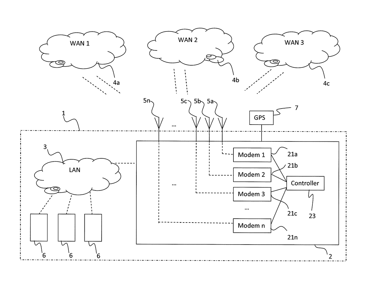
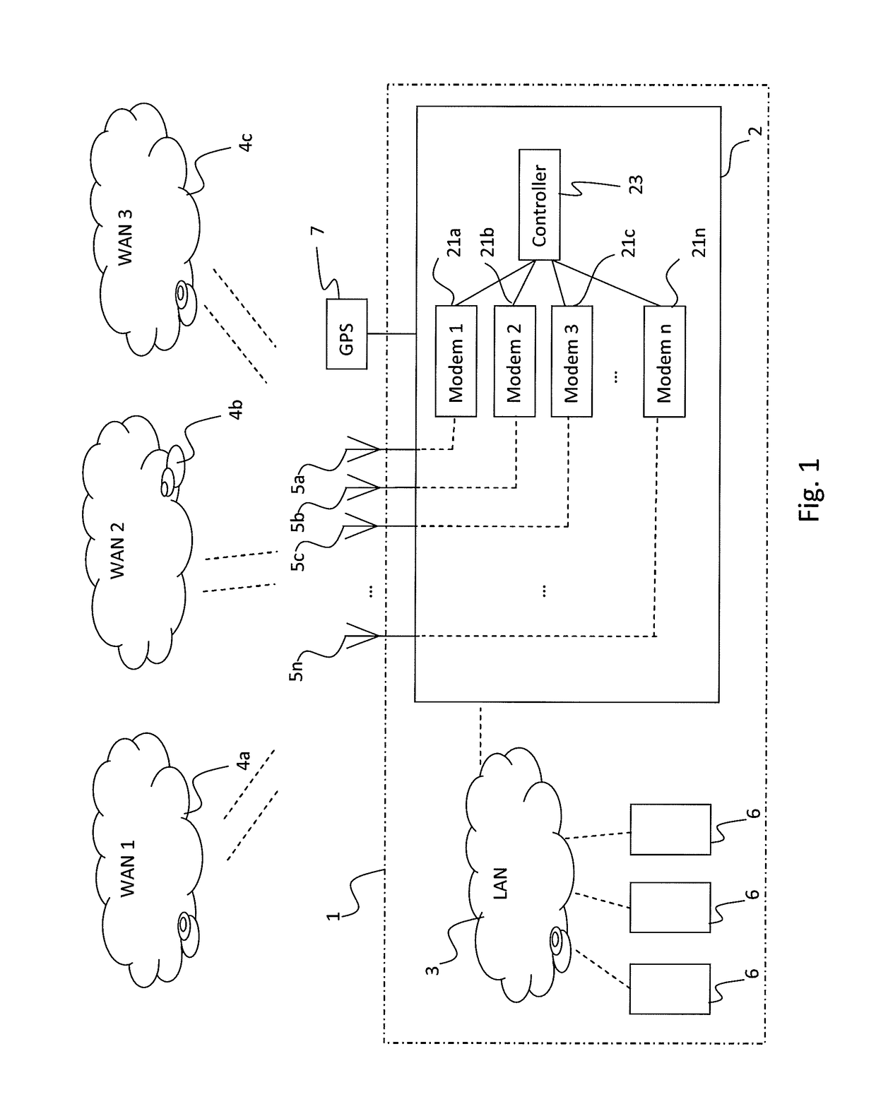
[0058]In FIG. 1 a s...


PUM


Abstract

A method and system for wireless communication with a mobile router in a moving vehicle, such as a train, and an external wireless network is disclosed. The external network includes a plurality of trackside base stations distributed along a path of travel. The method includes: determining the presence of a mobile router within the access area of a trackside base station, and when the presence of a mobile router has been determined: setting the power of the trackside base station to a high power mode; determining a direction of travel of the vehicle; setting the power of at least one trackside base station arranged in the forward direction of the base station for which the mobile router has been detected to a high power mode; and setting the power of at least one trackside base station arranged in the backward direction of the base station to a low power mode.

Description

TECHNICAL FIELD OF THE INVENTION[0001]The present invention relates to a wireless communication method and system for moving vehicles, such as trains, and in particular a method / system allowing more efficient communication between the moving vehicle and a stationary external communication network with trackside base stations, e.g. using a WLAN standard, and in particular using the IEEE 802.11 standard.BACKGROUND[0002]The demands on wireless communication capabilities in today's society are increasing rapidly. In particular, fast and easily accessible communication is desired through hand-held devices over large areas. It is particularly challenging to achieve such communication for mobile devices which are moving, e.g. when moving over large distances with poor network coverage or when affected by unknown sources of noise interrupting a signal for communication, such as clients moving on e.g. trains, airplanes, and other types of moving vehicles. In particular, if a client, such as ...

Claims


Application Information

Patent Timeline
Patent Type & Authority Applications(United States)
IPC IPC(8): H04W36/16H04W36/08
CPCH04W36/165H04W36/08H04W88/10H04W84/005H04W84/12H04W48/04Y02B70/00Y02D30/70H04W52/00
Inventor KARLSSON, MATSEKLUND, PETER
Owner ECOMELA
Why Eureka
Try Eureka