Catheter delivery system for stent valve

a technology of stent valve and catheter, which is applied in the field of catheter delivery systems for stent valves, can solve the problems of difficult to discern orientation from the stent alone, and achieve the effect of convenient accurate positioning and deployment of stent valves, simple and effective us

Active Publication Date: 2017-08-10
BOSTON SCI LTD
View PDF4 Cites 30 Cited by
  • Summary
  • Abstract
  • Description
  • Claims
  • Application Information

AI Technical Summary

Benefits of technology

[0006]It may be desirable to provide a catheter delivery device for stent valves avoiding the shortcoming known in the art and specifically to provide a delivery catheter system allowing for a simple and effective use, to facilitate accurate positioning an

Problems solved by technology

For example, the stent in its collapsed or compressed form, may be so small and/or so deformed compare

Method used


Image

  • Catheter delivery system for stent valve
  • Catheter delivery system for stent valve
  • Catheter delivery system for stent valve

Examples


first embodiment

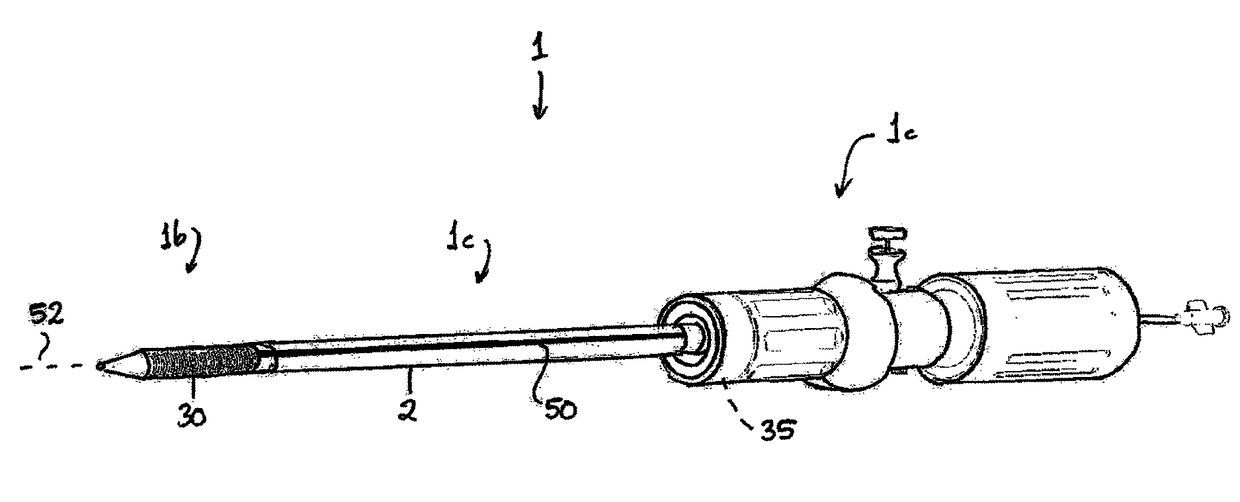
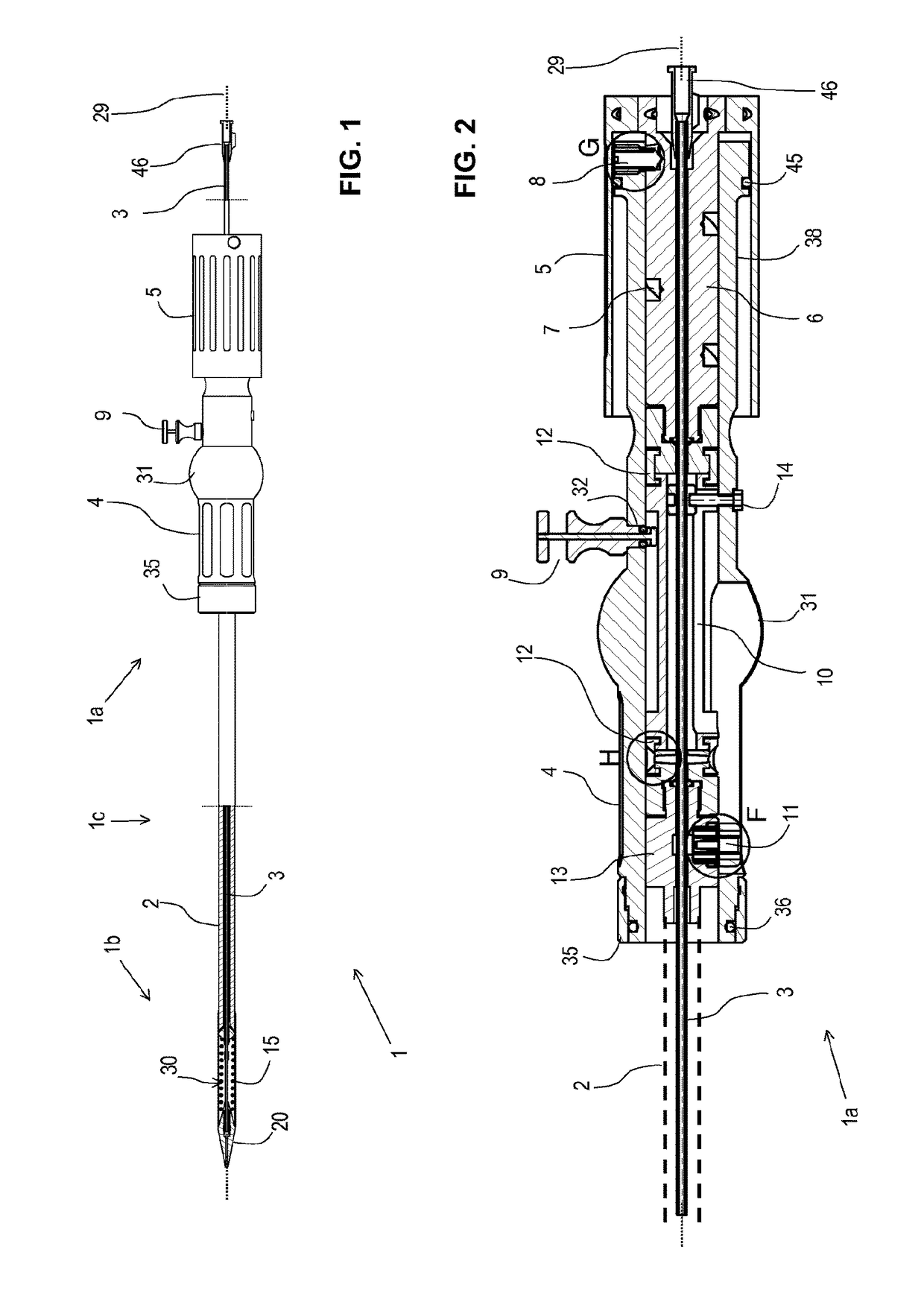
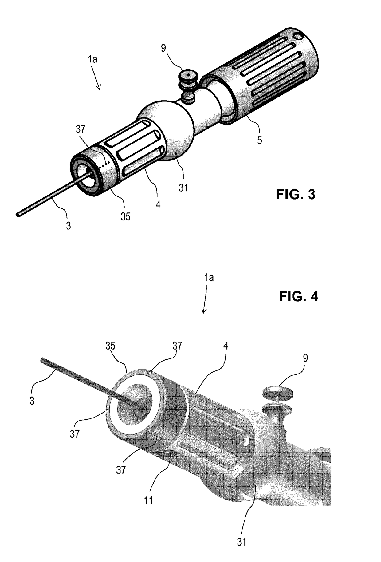
[0168]FIGS. 1-14 illustrate delivery catheter (also referred to as exemplary delivery device 1) for implanting a stent (e.g., valve stent or stent-valve) 15. The delivery catheter 1 comprises a proximal portion 1a to be held by an operator, a distal portion 1b for insertion into the body, and a stem or barrel portion 1c extending between the proximal and distal portions.

[0169]A sheath 2 may extend from the proximal portion 1a to the distal portion 1b where it may cover at least partly a stent 15 accommodated at a stent receiving portion 30, and arranged on tube member 3. Tube member 3 may further comprise a lumen adapted for the insertion of a guide wire 29. The tube member 3 may extend through a handle 4 at the proximal portion 1a. The handle 4 may comprise an actuator for controlling and / or driving linear translation of the sheath 2 in the proximal and / or distal direction(s). Translation of the sheath in e.g., the proximal direction may uncover the stent to deploy or allow deploym...

embodiment 1

[0199]FIG. 15 shows an alternative embodiment 1 of the catheter delivery device 1 according to the present disclosure. A stent attachment region 28 is located at the distal end of the catheter device, holding the catheter 15. At its most distal tip, the conical section 14 is arranged. The sheath 2 extends from the handle 4 located at the proximal end of the catheter device 1 to the distal end. As such, the sheath 2 may at least partially or completely circumferentially cover the stent 15. Tube member 3 extends along the entire length of the delivery device 1 and comprises a guide wire 29. In this embodiment, the actuation means are configured as trigger element 5. The handle 4 comprises a pistol grip 31 to enable a safe and easy handling of the catheter device by an operator. The device 1 further comprises braking means 9 configured as cylindrical, optionally self turning, threaded element. The threaded element may be analogous to the threaded element 6 as shown on FIG. 4. Said thre...


PUM


Abstract

A delivery catheter for a stent. The delivery catheter may comprise a distal end and a proximal end. The distal end includes a stent attachment region adapted to receive a stent. The stent may be of the self-expanding type. The catheter further comprises a handle at its proximal end and at least one sheath which may at least partially circumferentially cover said stent such as to retain it in a collapsed configuration. The sheath is coupled at its proximal end to an actuator located on said handle portion. The catheter further comprises at least one radio-opaque indicator for indicating a rotational orientation of the delivery catheter and/or the stent when observed using medical imaging during implantation of the stent.

Description

FIELD OF THE DISCLOSURE[0001]The present disclosure relates to catheter delivery systems for stent valves according to the independent claims.[0002]Background to the Disclosure[0003]Conventional approaches for cardiac valve replacement require the cutting of a relatively large opening in the patient's sternum (“sternotomy”) or thoracic cavity (“thoracotomy”) in order to allow the surgeon to access the patient's heart. Additionally, these approaches require arrest of the patient's heart and a cardiopulmonary bypass (i.e., use of a heart-lung bypass machine to oxygenate and circulate the patient's blood). In recent years, efforts have been made to establish a less invasive transcatheter cardiac valve replacement procedure, via either a transvascular approach, i.e. delivering the new valve through the femoral artery, or by transapical route, where the replacement valve is delivered between ribs and directly through the wall of the heart to the implantation site.[0004]Valve stents for u...

Claims


Application Information

Patent Timeline
IPC IPC(8): A61F2/24A61B90/00A61F2/95A61M25/01A61F2/966A61F2/97
CPCA61F2/2436A61F2/966A61F2/97A61F2/2427A61F2/95A61F2250/0098A61B90/39A61F2250/0087A61F2250/0089A61F2250/0097A61M25/0108A61B2090/0811A61B2090/3966A61F2/9517
Inventor DELALOYE, STEPHANEHEFTI, JEAN-LUCLOMBARDI, FABIENSIMONIN, PIERRE
Owner BOSTON SCI LTD
Why Eureka
Try Eureka