Corner structure of LNG storage tank

a technology of lng storage tanks and corners, which is applied in the direction of vessel construction details, transportation and packaging, mechanical equipment, etc., can solve the problems of complicated structure of connecting the secondary sealing wall difficult installation of the heat insulating wall, and complicated structure of the lng storage tank connection wall, etc., to improve workability, improve sealing reliability, and simplify the structure

Active Publication Date: 2017-08-10
KC LNG TECH CO LTD
View PDF1 Cites 11 Cited by
  • Summary
  • Abstract
  • Description
  • Claims
  • Application Information

AI Technical Summary

Benefits of technology

[0045]As described above, according to the present invention, it is possible to provide a corner structure of an LNG storage tank which can simplify the structures of a heat insulating wall and a sealing wall and the coupling structure thereof, improve workability, increase sealing reliability, is simple to assemble and manufacture to shorten the construction time of the storage tank, and allows a corner of the storage tank to effectively eliminate mechanical stresses generated in the storage tank.

Problems solved by technology

In the typical LNG storage tank, the heat insulating wall structure is composed of the primary and secondary heat insulating walls and the primary and secondary sealing walls and thus has a complicated structure.
In addition, the structure for connecting the secondary sealing wall of the LNG storage tank is complicated and installation of the heat insulating wall is not easy.
Further, there is a possibility that sealing reliability of the secondary sealing wall is reduced, causing LNG leakage, since the structure of a connection of the anchor structure or the secondary sealing wall is complicated and installation of the anchor structure or the secondary sealing wall is difficult.
In addition, the typical corner structure 20, which only supports the load of LNG applied to the sealing wall 50 without supporting the sealing wall 50, has a problem in absorption of stress due to thermal deformation of the storage tank caused by loading / unloading of LNG at extremely low temperature or due to deformation of the hull.

Method used


Image

  • Corner structure of LNG storage tank
  • Corner structure of LNG storage tank
  • Corner structure of LNG storage tank

Examples


Embodiment Construction

[0057]Hereinafter, exemplary embodiments of the present invention will be described in detail with reference to the accompanying drawings. It should be understood that the present invention may be embodied in different ways and is not limited to the following embodiments.

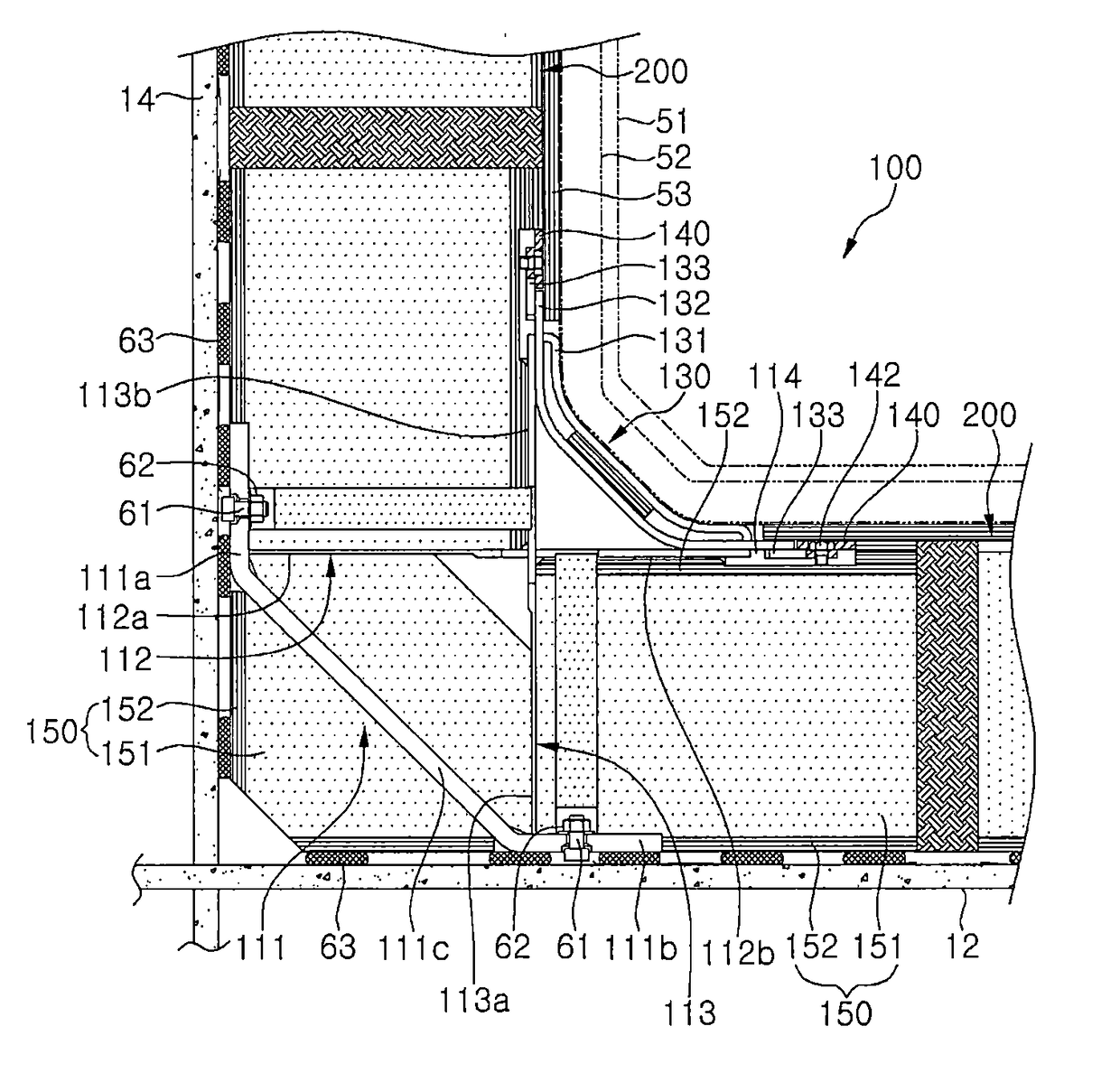
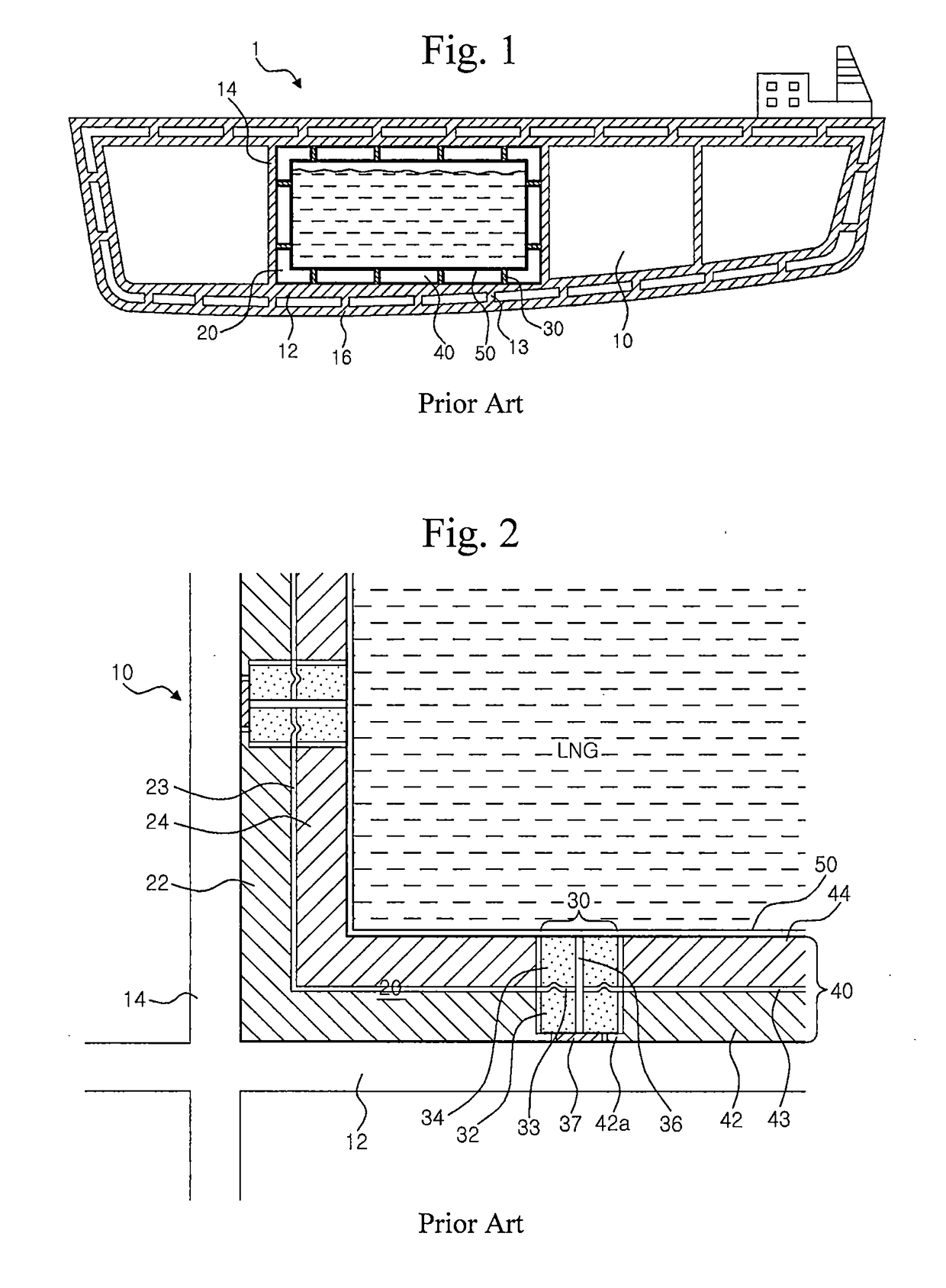
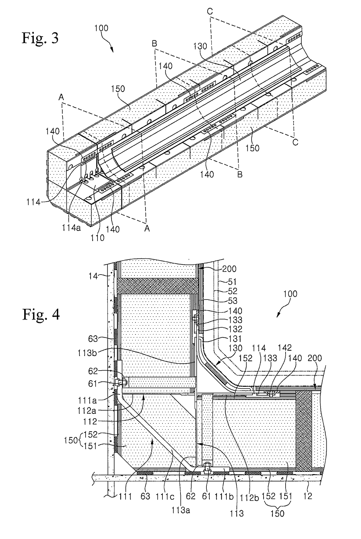
[0058]Referring to FIGS. 3 to 6, a corner structure 100 according to an exemplary embodiment of the present invention includes a securing member 110 or 110a secured to an inner surface of a storage tank 10 (see FIG. 1), i.e. a surface of a hull structure such as an inner wall 12 (see FIG. 1) and a bulkhead 14 (see FIG. 1); a movable member 130 supported on the securing member 110 and joined to a sealing membrane 51, 52; and a heat insulating member 150 disposed around the securing member 110.

[0059]Here, the movable member is linearly movable with respect to the securing member to a slight degree, as described below, upon thermal deformation due to temperature changes caused by loading / unloading of ultra-low temperat...


PUM


Abstract

A corner structure comprises: a fixed member fixed to a corner of a storage tank; a movable member supported on the fixed member so as to be linearly movable; a stop member attached to the fixed member to prevent the movable member from being detached from the fixed member; and a heat insulating member disposed between a sealing wall and a hull. The fixed member comprises a guide portion provided with a guide recessed portion, the movable member comprises a guide protruding portion inserted into the guide recessed portion, and the width and the length of the guide protruding portion are smaller than the width and the length of the guide recessed portion, so that the movable member can be supported on the fixed member to be movable in the longitudinal direction and in the direction perpendicular to the longitudinal direction.

Description

TECHNICAL FIELD[0001]The present invention relates to a corner structure of an LNG storage tank, and, more particularly, to a corner structure arranged to provide a heat insulating wall and a sealing wall on an inner wall surface of an LNG storage tank for storing liquefied natural gas which has a liquid phase at ultra-low temperature.BACKGROUND ART[0002]Liquefied natural gas (LNG) is obtained by liquefying natural gas, one of the fossil fuels, and LNG storage tanks may be divided into onshore storage tanks installed on the ground or buried in the ground or mobile storage tanks installed in vehicles such as automobiles and ships, depending on installation location.[0003]Since LNG has a danger of explosion when exposed to impact and is kept in a cryogenic state, a storage tank for LNG has a structure in which impact resistance and liquid tightness are maintained firmly.[0004]In addition, in contrast to onshore storage tanks where sloshing of LNG is negligible, LNG storage tanks insta...

Claims


Application Information

Patent Timeline
Patent Type & Authority Applications(United States)
IPC IPC(8): F17C3/02F17C3/04B63B25/16
CPCF17C3/025B63B25/16F17C3/04F17C2223/0161F17C2221/033F17C2203/0639F17C2270/0105F17C2203/03F17C1/12F17C3/027F17C2201/0157F17C2201/052F17C2203/0358F17C2203/0617F17C2223/033F17C2260/013F17C2270/0107
Inventor HAN, HAE CHULYOON, IHN SOOSEO, HEUNG SEOKCHO, YONG BUMKIM, YOUNG KYUNJIN, KYO KOOKLEE, YEONG BEOMCHOE, KUN HYUNG
Owner KC LNG TECH CO LTD
Why Eureka
Try Eureka