
High-resolution scanning microscopy with discrimination between at least two wavelength ranges

a scanning microscopy and high-resolution technology, applied in the field of high-resolution scanning microscopy, can solve the problems of reducing the resolution of light microscopes, significantly improving the resolution below the diffraction limit, and requiring a color splitter with a corresponding detector

Active Publication Date: 2017-08-10
CARL ZEISS MICROSCOPY GMBH
View PDF1 Cites 8 Cited by
  • Summary
  • Abstract
  • Description
  • Claims
  • Application Information

AI Technical Summary

Benefits of technology

The invention aims to develop a method and microscope that can capture color information without requiring extensive adjustment for multiple color channels.

Problems solved by technology

In principle, the optical resolution of a light microscope, including that of an LSM, is diffraction-limited by the laws of physics.
This does not lead to a considerably improved resolution below the diffraction limit of the microscope.
However, it has the disadvantage that one color splitter with corresponding detector is needed for each color channel.
In the case of conventional laser scanning microscopy, which uses a non-spatially resolving detector behind a confocal pinhole diaphragm (so-called pinhole), this requirement is largely unproblematical; in the case of an oversampling two-dimensional detector according to EP 2317362 A1 a considerable cost arises, however, especially because such two-dimensional detectors are expensive.

Method used


Image

  • High-resolution scanning microscopy with discrimination between at least two wavelength ranges
  • High-resolution scanning microscopy with discrimination between at least two wavelength ranges
  • High-resolution scanning microscopy with discrimination between at least two wavelength ranges

Examples


Embodiment Construction

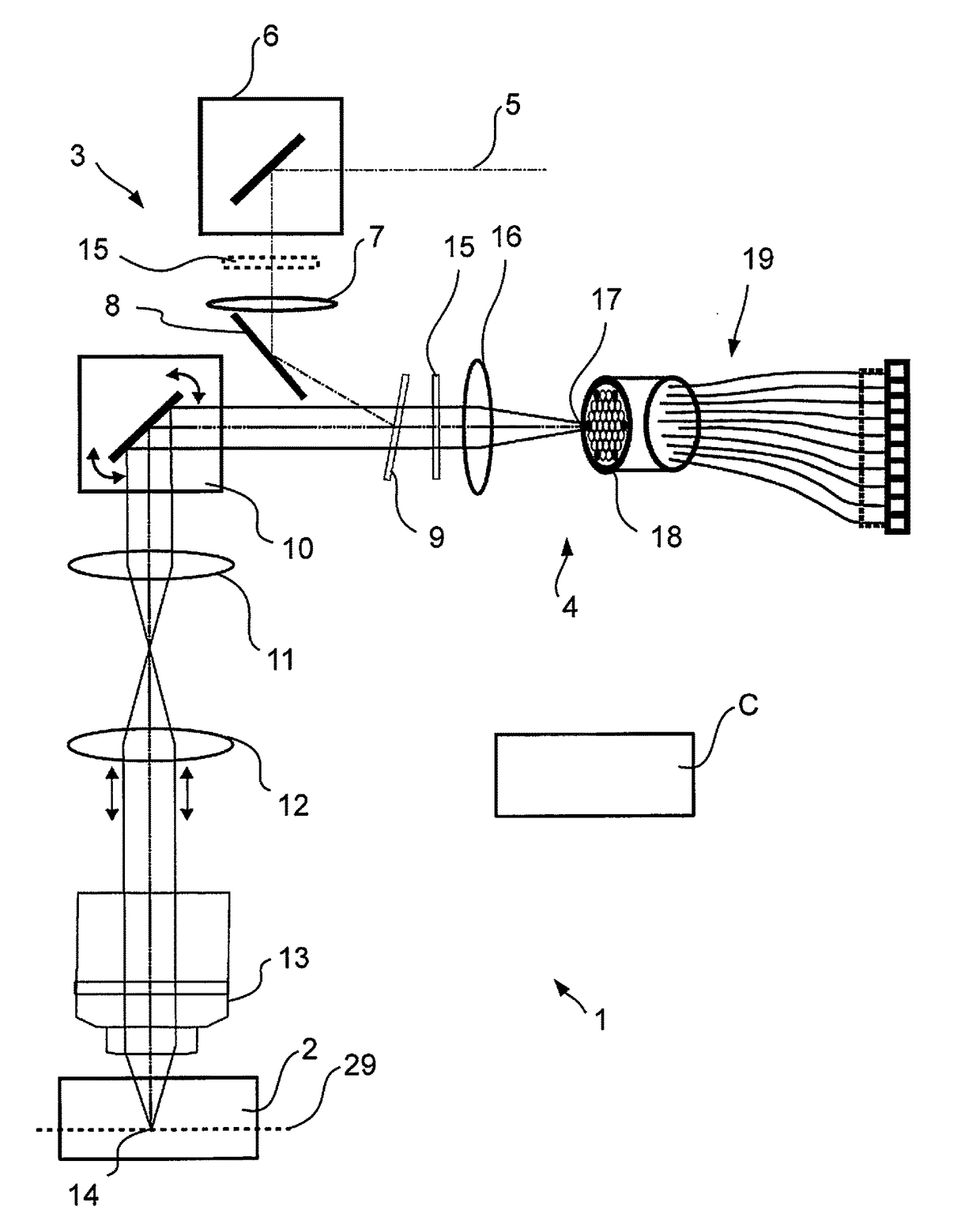
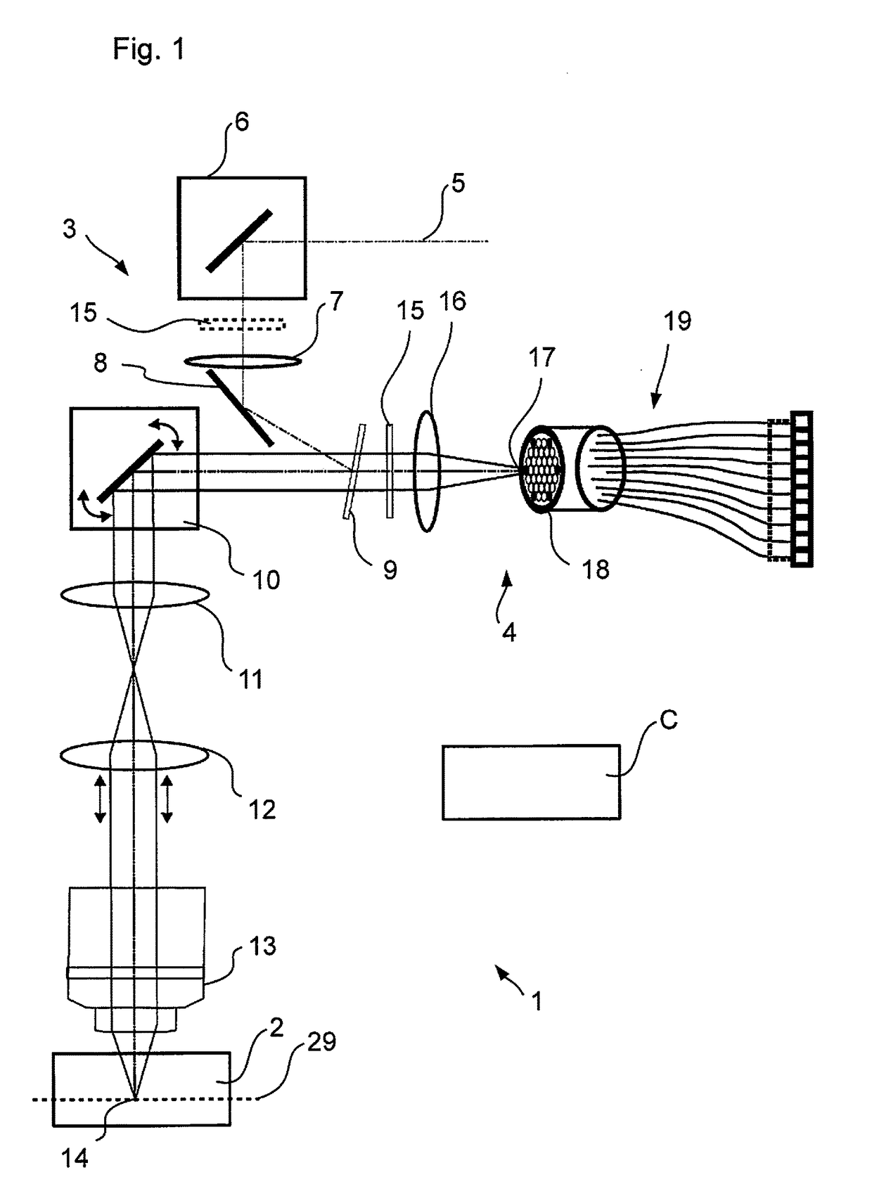
[0039]FIG. 1 shows a laser scanning microscope 1 schematically that is adapted for microscopy of a sample 2. The laser scanning microscope 1 (abbreviated to LSM in the following) is controlled by a control device C and comprises an illumination beam path 3 as well as an imaging beam path 4. The illumination beam path illuminates a spot in the sample 2 and the imaging beam path 4 images this spot in a diffraction-limited manner for detection. Illumination beam path 3 and imaging beam path 4 share a lens system.

[0040]The LSM 1 illuminates the sample 2 by means of a laser beam 5 provided which is guided to a mirror 8 via an optional deflecting mirror 6 and a lens 7. The mirror 8 ensures that the laser beam 5 is incident on a coupling-in element, e.g., an emission filter 9, under an angle of reflection. For a clearer representation, only the main axis of the laser beam 5 is shown.

[0041]After reflection at the emission filter 9, the laser beam 5 is deflected biaxially by a scanner 10 and...


PUM


Abstract

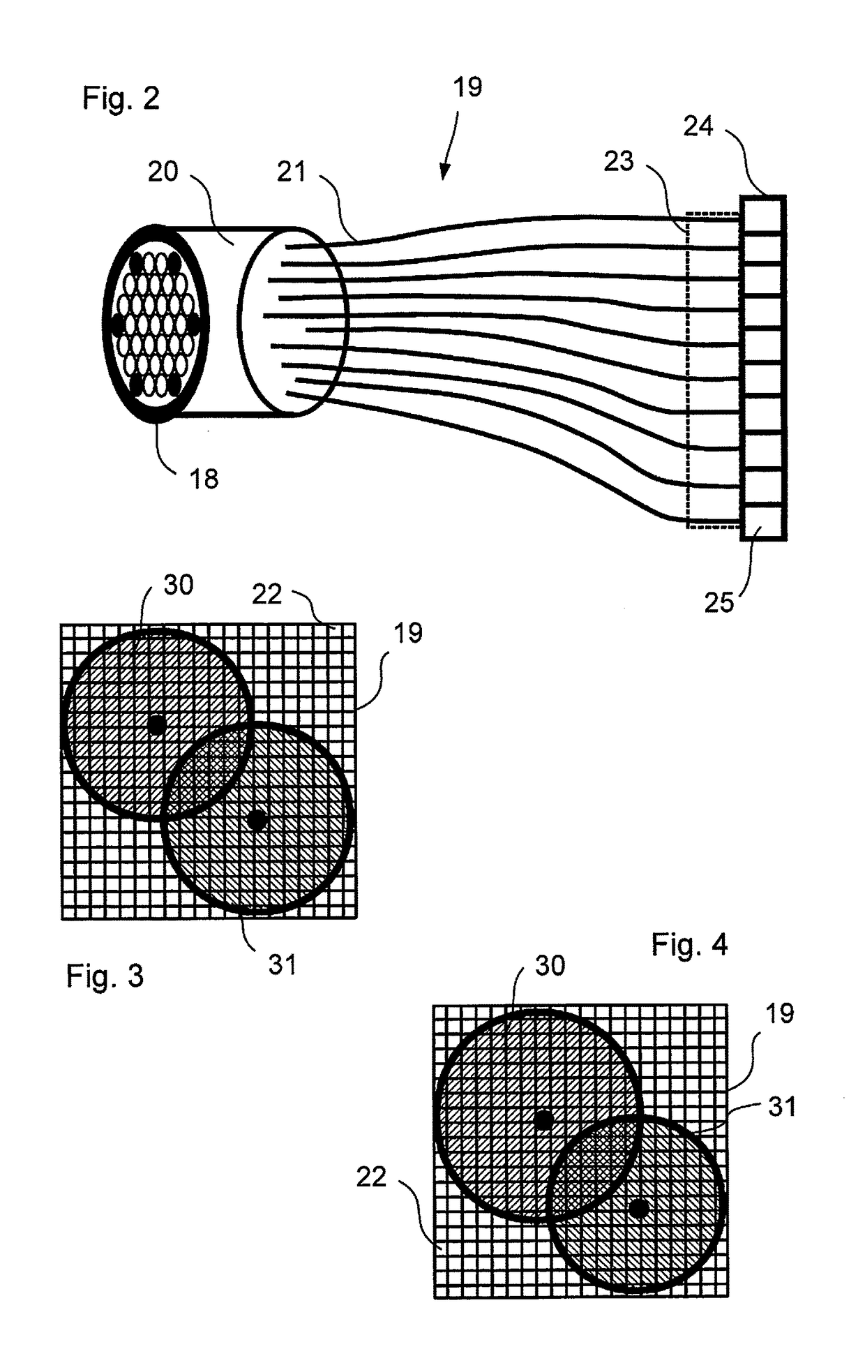
A microscopy high-resolution scanning method, including exciting a sample with illumination radiation focused at a point to form a diffraction-limited illumination spot so as to emit fluorescence radiation. The point is imaged in a diffraction image on a spatially resolving two-dimensional detector. The sample is scanned at scanning positions with increments that are smaller than half the diameter of the spot. An image of the sample with a resolution increased beyond a resolution limit of the image is generated from the data of the two-dimensional detector and the scanning positions. To discriminate between at least two predetermined wavelength ranges in the fluorescence radiation of the sample, Airy disks corresponding to the wavelength ranges are generated on the two-dimensional detector, the Airy disks being offset laterally from one another such that the diffraction image consists of the mutually offset Airy disks. The Airy disks are evaluated when generating the sample image.

Description

PRIORITY CLAIM[0001]The present application is a National Phase entry of PCT Application No. PCT / EP2015 / 068113, filed Aug. 5, 2015, which claims priority from German Patent Application Number 102014111167.2, filed Aug. 6, 2014, the disclosures of which are hereby incorporated by reference herein in their entirety.FIELD OF THE INVENTION[0002]The invention relates to a method for high-resolution scanning microscopy of a sample, wherein the sample is excited by illumination radiation to emit fluorescent radiation, wherein the illumination radiation is focused to a point in or on the sample to form a diffraction-limited illumination spot, the point is imaged to a diffraction image on a spatially resolving two-dimensional detector in diffraction-limited manner, wherein the two-dimensional detector has a spatial resolution which resolves a diffraction structure of the diffraction image, the point is displaced into various scanning positions relative to the sample with an increment which i...

Claims


Application Information

Patent Timeline
Patent Type & Authority Applications(United States)
IPC IPC(8): G02B21/00
CPCG02B21/0072G02B21/008G02B21/0076G02B21/0032G02B27/58G01N21/6458
Inventor KLEPPE, INGONETZ, RALFNOVIKAU, YAUHENI
Owner CARL ZEISS MICROSCOPY GMBH
Learn More