Exhaust gas purification apparatus for internal combustion engine
a technology of exhaust gas purification apparatus and internal combustion engine, which is applied in the direction of mechanical apparatus, engine components, machines/engines, etc., can solve the problems of clogging of the addition valve, abrasion of sliding parts in the addition valve, and inability to supply urea solution, etc., to achieve the effect of preventing or reducing abrasion
- Summary
- Abstract
- Description
- Claims
- Application Information
AI Technical Summary
Benefits of technology
Problems solved by technology
Method used
Image
Examples
first embodiment
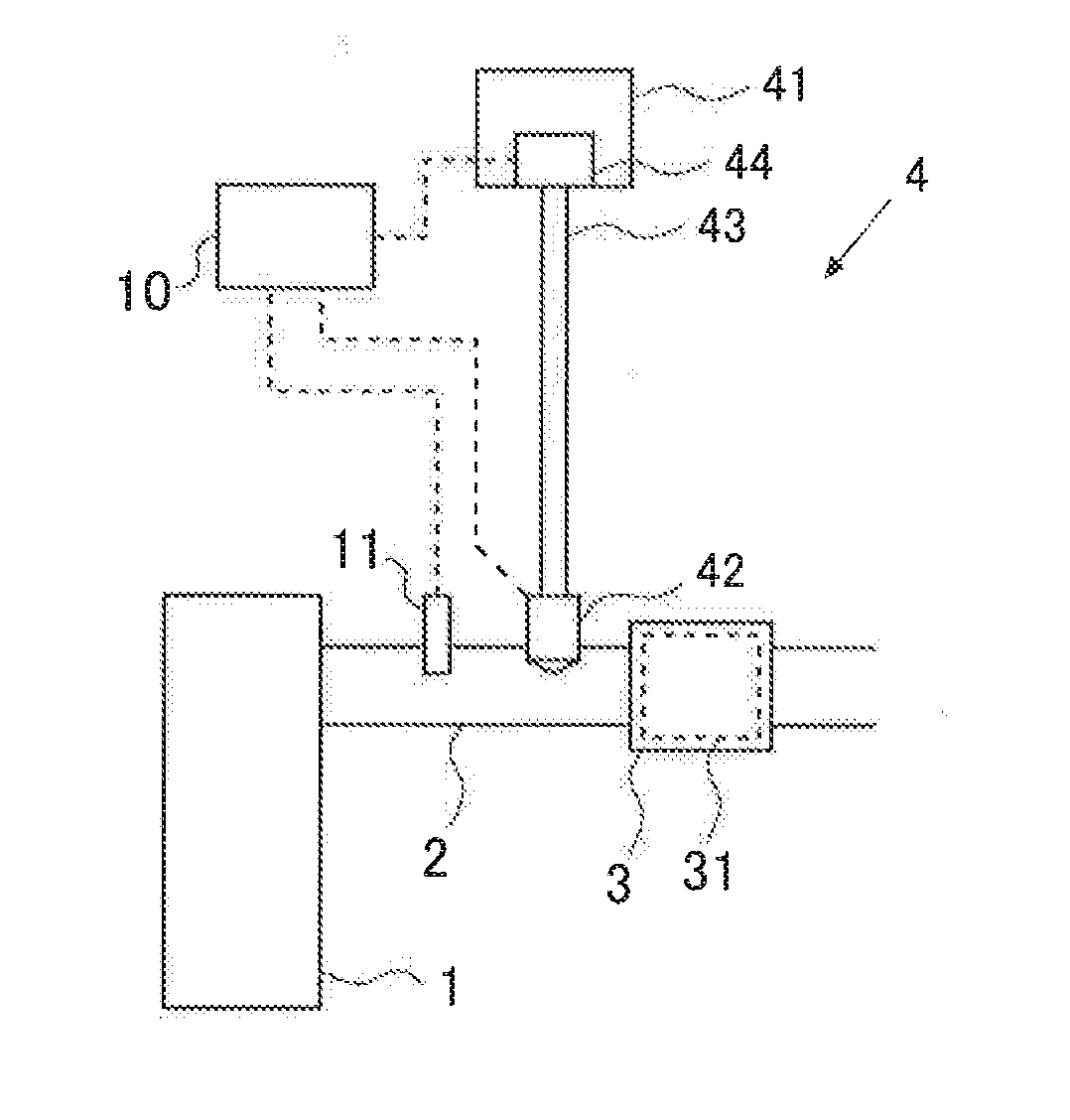
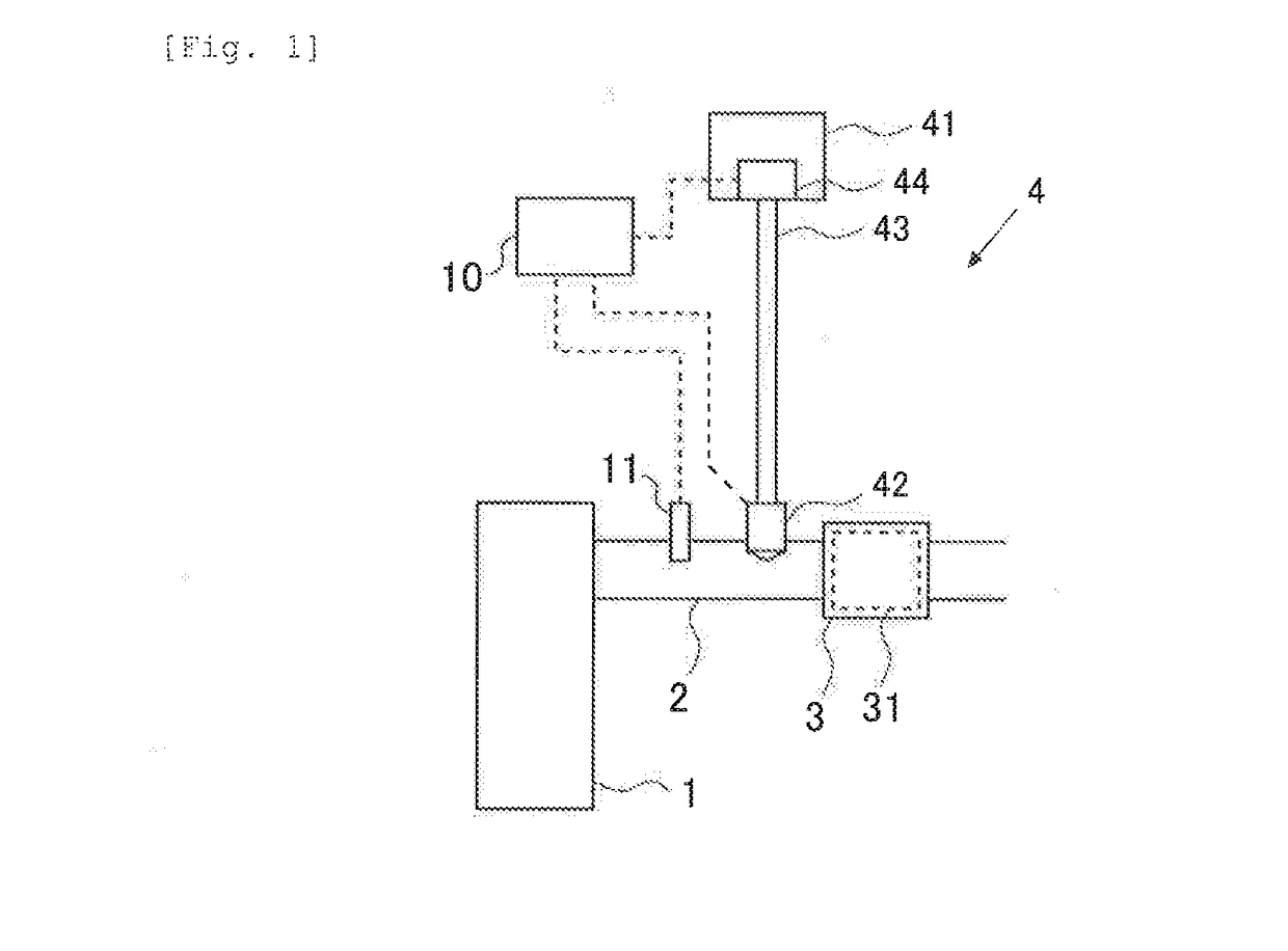
[0039]FIG. 1 is a diagram showing the general configuration of the exhaust system of an internal combustion engine according to a first embodiment. The internal combustion engine 1 is a diesel engine for driving a vehicle. It will be appreciated that the internal combustion engine 1 according to the embodiment is not limited to a diesel engine, but it may be a gasoline or other engine.
[0040]The internal combustion engine 1 is connected with an exhaust passage 2. The exhaust passage 2 is provided with a filter 3 on which a selective catalytic reduction NOx catalyst 31 that selectively reduces NOx in the exhaust gas using ammonia as reducing agent is supported. The selective catalytic reduction NOx catalyst 31 will be hereinafter referred to as the “SCR catalyst 31”. The filter 3 is a wall-flow filter, which traps PM in the exhaust gas. The SCR catalyst 31 adsorbs ammonia and reduces NOx in the exhaust gas using ammonia as reducing agent. While the SCR catalyst 31 is supported on the ...
second embodiment
[0087]A second embodiment will be described. In the second embodiment, if there is a possibility that the particle diameter of the precipitates may exceed the allowable range during the period between the end of the first control and the start of the second control, the ECU 10 causes the addition valve 42 to inject urea solution into the exhaust passage 2.
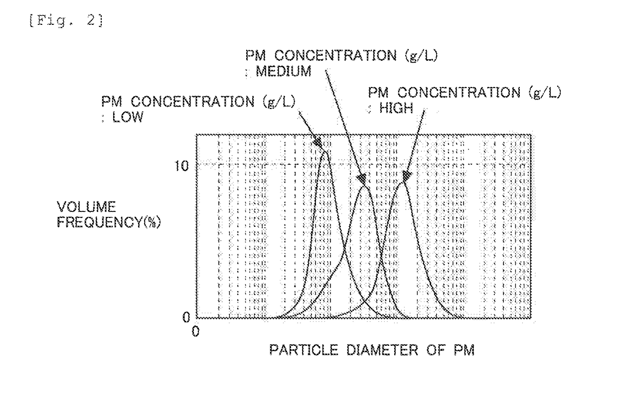
[0088]Even if the first control has been performed, a very small quantity of urea solution may remain in spaces between components of the addition valve 42 in some cases. At the time when the first control is performed, the temperature of the exhaust gas of the internal combustion engine 1 in the exhaust passage 2 is still high, and high-temperature exhaust gas flows into the addition valve 42 by the first control. During the first control, PM in the exhaust passage 2 is also sucked into the addition valve 42. Therefore, if the first control is performed immediately after the internal combustion engine 1 is stopped, the concentrati...
third embodiment
[0105]In the above-described first and second embodiments, the first control and the second control are performed in any case. However, in cases where the exhaust gas temperature at the time when the internal combustion engine 1 is stopped is lower than the predetermined temperature, the particle diameter of the precipitates in the addition valve 42 does not increase so much even if the urea solution in the addition valve 42 and the area solution channel 43 is sucked thoroughly back into the tank 41. In such cases, it is not necessary to perform the first control. In this third embodiment, it is determined whether or not it is necessary to perform the first control, on the basis of the exhaust gas temperature at the time when the internal combustion engine 1 is stopped. In cases where it is not necessary to perform the first control, the urea solution in the addition valve 42 and the urea solution channel 43 is sucked thoroughly back into the tank 41 at one time. The control by whic...
PUM
 Abstract
Description
Claims
Application Information
 - R&D
- Intellectual Property
- Life Sciences
- Materials
- Tech Scout
- Unparalleled Data Quality
- Higher Quality Content
- 60% Fewer Hallucinations
Browse by: Latest US Patents, China's latest patents, Technical Efficacy Thesaurus, Application Domain, Technology Topic, Popular Technical Reports.
© 2025 PatSnap. All rights reserved.Legal|Privacy policy|Modern Slavery Act Transparency Statement|Sitemap|About US| Contact US: help@patsnap.com


