Thread Shaped Contact Electrification Fiber

a fiber and contact technology, applied in textiles, protective garments, textiles and papermaking, etc., can solve the problems of low piezoelectric power, unsuitable wearable electronics, and frequent recharging,

Inactive Publication Date: 2017-08-17
UNIVERSITY OF MISSOURI
View PDF1 Cites 7 Cited by
  • Summary
  • Abstract
  • Description
  • Claims
  • Application Information

AI Technical Summary

Problems solved by technology

Although promising [3-5], the power produced by piezoelectrics is so low that they are not satisfactory for many applications.
Currently, one of the most common power sources for mobile electronics is the lithium-ion battery, but it is not appropriate for wearable electronics because of the potential fire hazard of lithium in air, in addition to the large size and heavy weight.
Another drawback is the requirement for frequent recharging.
Although various alternative methods of harvesting power from solar, [21] wind, [22] mechanical vibration, [23] etc. have been considered; size and weight are not easily reduced in order to be compatible with wearable electronics.
Many energy conversion mechanisms require certain devices and materials which cannot be miniaturized to be unnoticeably hidden in textiles.
The electrostatic charge imbalance between materials drives charges from one material to the other.
However, all these approaches resulted in relatively large power sources to attach to clothes.

Method used


Image

  • Thread Shaped Contact Electrification Fiber
  • Thread Shaped Contact Electrification Fiber
  • Thread Shaped Contact Electrification Fiber

Examples


example 1

re

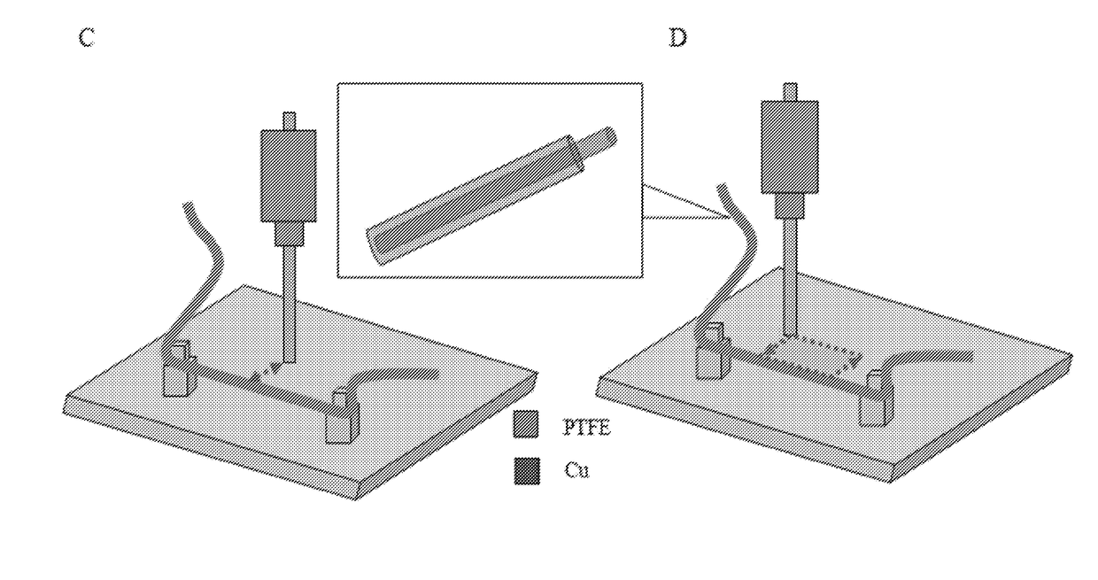
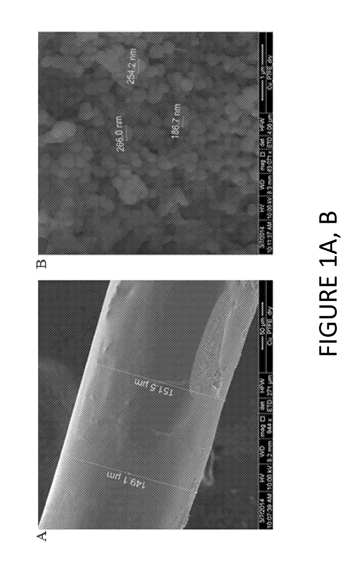
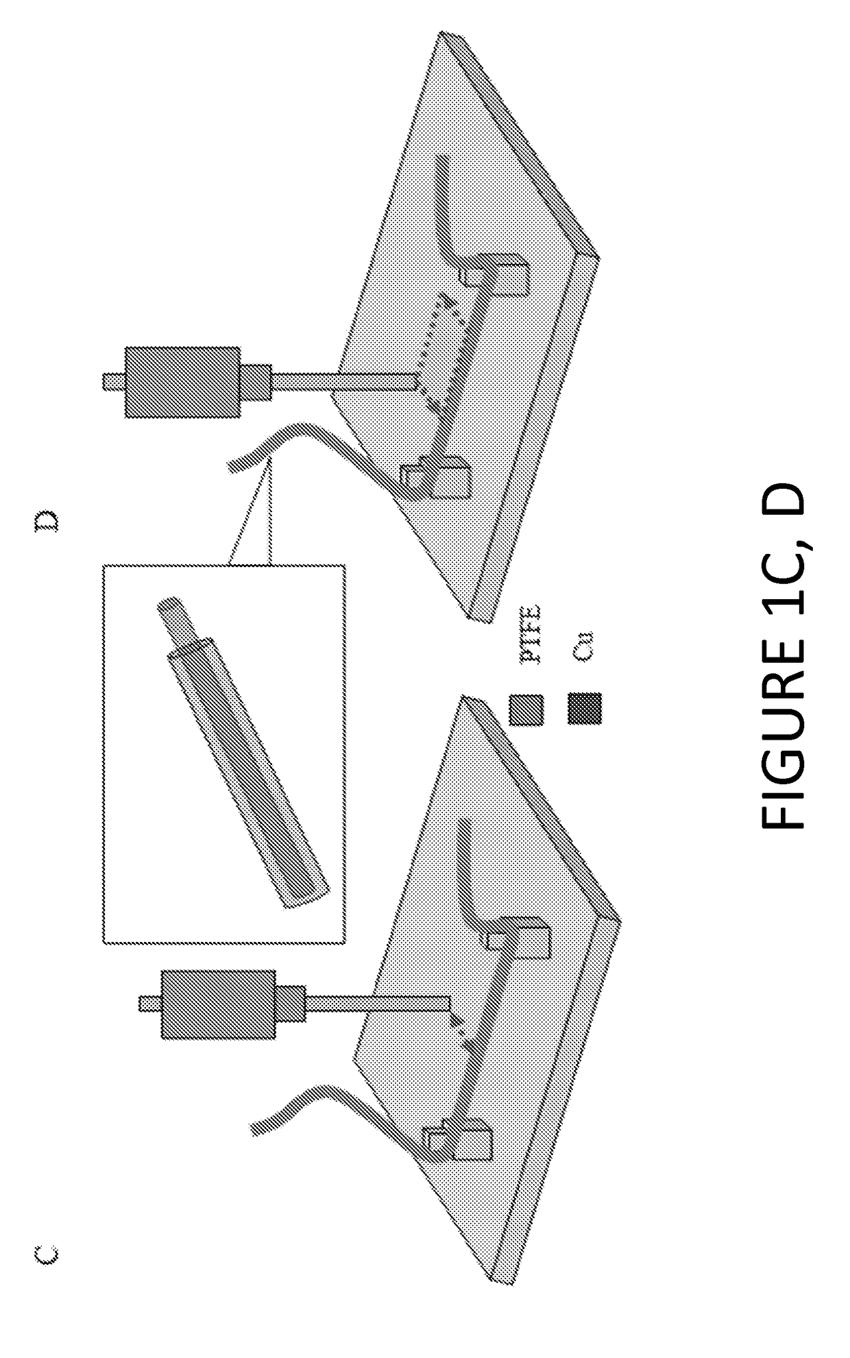
[0056]As illustrated in FIG. 1, a representative contact electrification fiber consists of a fine copper line (130 μm) coated with a very thin layer (10 μm) of polytetrafluoroethylene (PTFE). FIG. 1a shows a SEM image of the contact electrification fiber (i.e., a copper wire of diameter of 130 μm wrapped with PTFE nanoparticles). The diameter of the PTFE-coated wire is about 150 μm as shown. Copper was selected because of its high conductivity, mechanical strength, and cost efficiency. Using copper as a core of the fiber also allows high temperature treatment of the PTFE coating layer. The heating process helps PTFE particles bond more strongly to each other, which significantly reduces the possibility of them detaching from the final product in use. PTFE was selected as the contact electrification material because it is one of the most negative contact electrification materials. With a solution of 60% dispersion PTFE in water, a thin layer of PTFE was coated on fine copper wires ...

example 2

reads

[0063]Among the fabrics used for textile and apparel manufacturing, cotton (natural cellulose) is the most commonly used material due to its processing simplicity, cost effectiveness, mechanical properties and overall comfort. In addition, various methods of treating cotton without losing cotton's unique set of physical properties have been broadly studied. [24-33] Therefore, cotton was used as a base substrate material for a thread-based wearable power harvester. Carbon black particles were embedded within cotton threads for enhancing electrical conductive properties. The structure of the thread-based power harvester is depicted in FIG. 5a. Carbon nanotubes (CNTs) are considered to be good conductive materials, but are very expensive. [35] A carbon-activated thread (CAT) power harvester, however, can be easily and cost-effectively produced with standard cotton materials imbued with carbon black particles. Polydimethylsiloxane (PDMS) may also be used to enhance the stability of...


PUM

PropertyMeasurementUnit
resistivityaaaaaaaaaa
diameteraaaaaaaaaa
cross-sectional distanceaaaaaaaaaa

Abstract

An electrostatic power generation fiber comprising a thread-shaped core that comprises a conductive component; a charge building-inducting-tunneling layer on the core that comprises a contact electrification material. An embodiment of the present invention is directed to an electrostatic power generation fiber comprising: (a) a thread-shaped core that comprises a conductive component; and (b) a charge building-inducting-tunneling layer on the core that comprises a contact electrification material; wherein electrical charge, formed via contact electrification of the charge building-inducting-tunneling layer, travels along the core, which during electrostatic power generation the core is a constituent of an electrical network.

Description

CROSS-REFERENCE TO RELATED APPLICATIONS[0001]The present application is a PCT application claiming the benefit of U.S. Provisional Application 62 / 038,666, filed Aug. 18, 2014, and U.S. Provisional Application 62 / 131,012, filed Mar. 10, 2015, which are incorporated herein by reference in their entirety.FIELD OF INVENTION[0002]The present invention is directed to contact electrification fibers that may be incorporated into textiles and garments for electrical power generation and methods of making such contact electrification fibers.BACKGROUND OF INVENTION[0003]In recent years, there has been remarkable growth in the diversity and application of small electronics, as evidenced by the increasing global prevalence of portable systems. Amazing advancements of micro / nanotechnologies have resulted in the emergence of new applications, including novel wearable electronics, the importance of which is on the rise. [13-20] There have been numerous attempts to develop various alternative energy...

Claims


Application Information

Patent Timeline
Patent Type & Authority Applications(United States)
IPC IPC(8): H02N1/04D03D15/02D03D1/00A41D1/00A41D31/00
CPCH02N1/04A41D1/002D03D15/02D03D1/0088A41D31/00D03D15/67
Inventor KWON, JAE WANNGUYEN, QUANGKIM, BAEK HYUN
Owner UNIVERSITY OF MISSOURI
Why Eureka
Try Eureka