Aircraft engine assembly, comprising an engine attachment device equipped with structural movable cowls connected to the central box

a technology for aircraft engines and attachment devices, which is applied in the direction of machines/engines, mechanical equipment, transportation and packaging, etc., can solve the problems of affecting the dimensioning of the surrounding aerodynamic, and the disturbance of aerodynamics, so as to improve reduce the bulk. , the effect of improving the overall performance of the engin

Active Publication Date: 2017-08-24
AIRBUS OPERATIONS (SAS)
View PDF0 Cites 14 Cited by
  • Summary
  • Abstract
  • Description
  • Claims
  • Application Information

AI Technical Summary

Benefits of technology

[0016]The invention is thus noteworthy in that it provides main ties in the form of three shearing pins distributed around the longitudinal axis of the engine, between the intermediate case, and the movable structural cowls and / or their connecting structure. The three radially oriented shearing pins alone make it possible to form an isostatic system for absorbing forces, within which most of the forces originating from the engine are absorbed, as close as possible to the center of gravity thereof.
[0017]Because of this, in the preferred embodiment in which secondary ties complement the main ties by being, for example, situated more towards the rear, these secondary ties are largely relieved of load by absorbing only the inertial loading of the central case of the engine. They can, because of this, have a smaller bulk than in the prior art. By virtue of this reduction of bulk, the secondary airflow is less disturbed in the secondary jet, which improves the overall performance of the engine. The surrounding aerodynamic fairings can also have a reduced bulk, with a positive consequential reduction of the drag and of their weight.

Problems solved by technology

This causes, in the secondary jet, aerodynamic disturbances which are detrimental to the overall performance of the engine.
Furthermore, it results in an over dimensioning of the surrounding aerodynamic fairings, such as the rear aerodynamic fairing (or Aft Pylon Fairing, APF), the width of which has to be adapted accordingly.
These over dimensionings of the surrounding fairings also cause drag.

Method used


Image

  • Aircraft engine assembly, comprising an engine attachment device equipped with structural movable cowls connected to the central box
  • Aircraft engine assembly, comprising an engine attachment device equipped with structural movable cowls connected to the central box
  • Aircraft engine assembly, comprising an engine attachment device equipped with structural movable cowls connected to the central box

Examples


Embodiment Construction

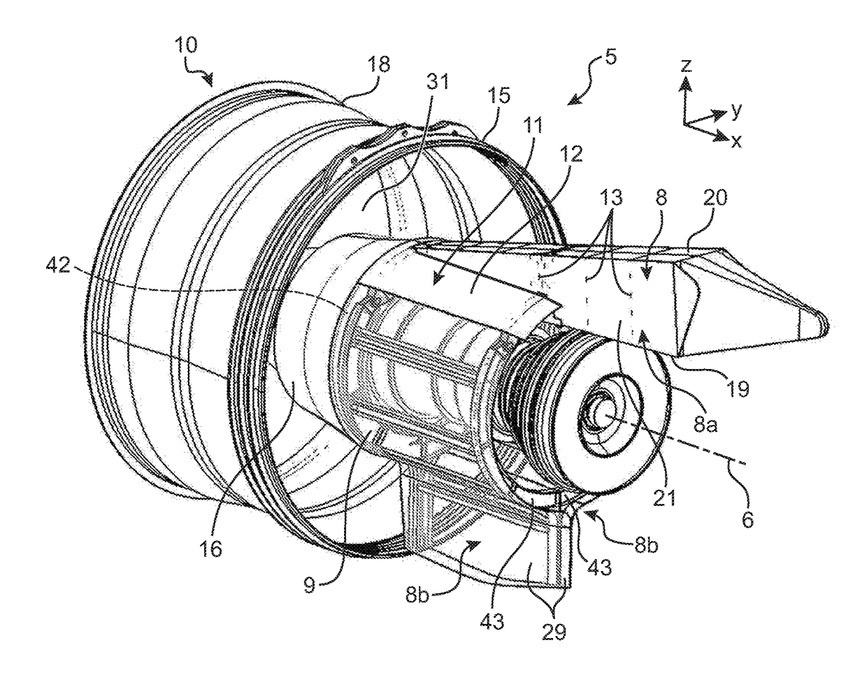
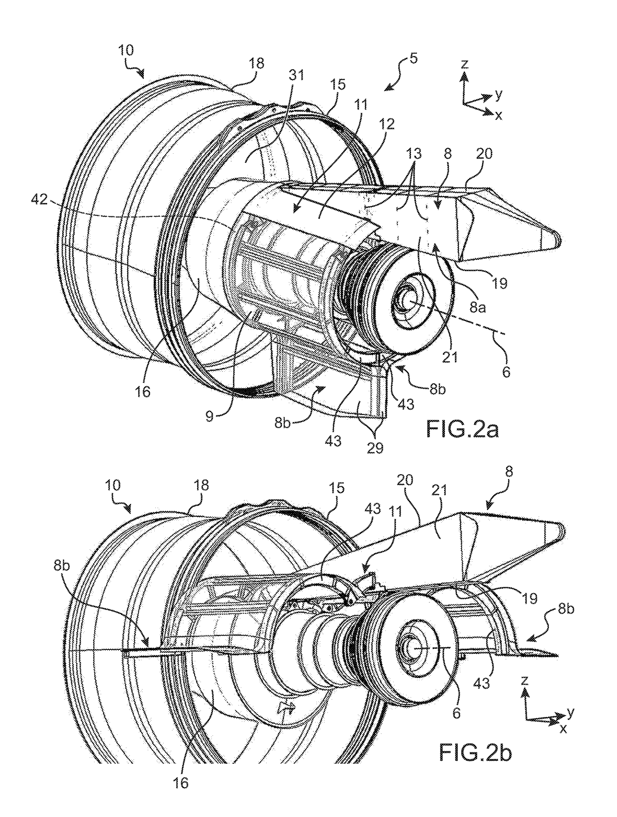
[0050]Referring to FIG. 14, an aircraft 200 is represented comprising a fuselage 3 on which are fixed two wing elements 2 (only one is visible in FIG. 11), each wing element bearing an engine assembly 5 according to the invention. This engine assembly 5 comprises a double-flow, double-body engine 10, such as a jet engine, and a device 4 for attaching the engine 10, also called an attachment strut. Conventionally, the engine assembly 5 is suspended under its wing 2.

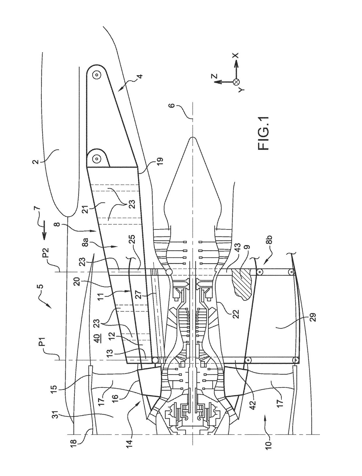
[0051]Referring to FIG. 1, one of the engine assemblies 5 is represented, fixed under its wing 2. The assembly 5 is intended to be surrounded by a nacelle (not represented), and the attachment device 4 comprises a series of ties (not referenced) added to the rigid structure 8 and making it possible to ensure the suspension of this assembly 5 under the wing 2 of the aircraft.

[0052]Throughout the following description, by convention, the direction X corresponds to the longitudinal direction of the device 4 which can also be ...


PUM


Abstract

In order to reduce the size of the attachment arrangement between an aircraft engine and its attachment device, an engine assembly is provided for which the primary structure of the attachment device includes a central box and two movable structural cowls. Further the arrangement for attaching the engine on the structure comprises a group of main ties laid out in a main transverse plane for absorbing forces crossing a front end of the movable structural cowls, this group comprising three main shearing pins radially oriented and distributed around a longitudinal axis of the engine, each pin crossing a first shearing orifice provided on a fitting secured to the hub of the intermediate case on the one hand, and a second shearing orifice provided on one of the movable cowls or on its connecting structure to the central box on the other hand.

Description

CROSS-REFERENCES TO RELATED APPLICATIONS[0001]This application claims the benefit of the French patent application No. 16 51468 filed on Feb. 23, 2016, the entire disclosures of which are incorporated herein by way of reference.TECHNICAL FIELD[0002]The present invention relates to the field of aircraft engine assemblies comprising a device for attaching the motor on a structure of the aircraft, preferably under a wing of this aircraft.[0003]It applies preferentially to commercial airplanes.BACKGROUND OF THE INVENTION[0004]In existing aircraft, the engines such as double-flow and double-body jet engines, are suspended under the wings or added to the fuselage by complex attachment devices, also called EMS (engine mounting structure), or even attachment strut. The attachment struts usually employed have a rigid structure, called primary structure. This primary structure generally forms a box, that is to say that it consists of the assembly of bottom and top spars connected together by ...

Claims


Application Information

Patent Timeline
Patent Type & Authority Applications(United States)
IPC IPC(8): B64D29/06B64D27/26
CPCB64D29/06B64D2027/264B64D27/26B64D27/18B64D2027/266B64D2027/262B64D27/16F02C7/20B64D2027/268
Inventor PAUTIS, OLIVIERLAFONT, LAURENTGOUGEON, PASCAL
Owner AIRBUS OPERATIONS (SAS)
Why Eureka
Try Eureka