Lubrication control device for transmission
a technology of lubrication control and transmission, which is applied in the direction of gearing details, belts/chains/gear parts, gear lubrication/cooling, etc., can solve the problems of affecting the warm-up of the transmission, the increase in the temperature of the hydraulic oil in the oil cooler may be slight, and the excessive flow rate of the hydraulic oil to the oil cooler, etc., to achieve the effect of reducing the flow rate of the oil flowing, reducing stirring loss and dragging loss loss
- Summary
- Abstract
- Description
- Claims
- Application Information
AI Technical Summary
Benefits of technology
Problems solved by technology
Method used
Image
Examples
first embodiment
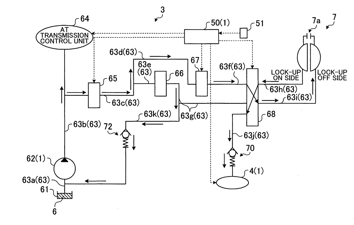
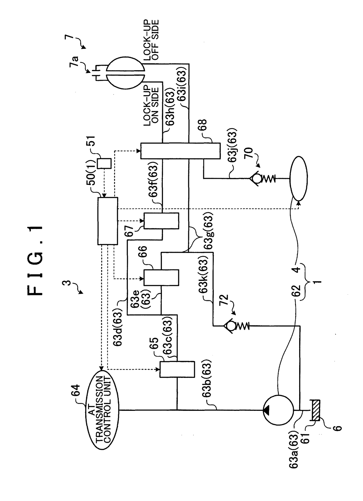
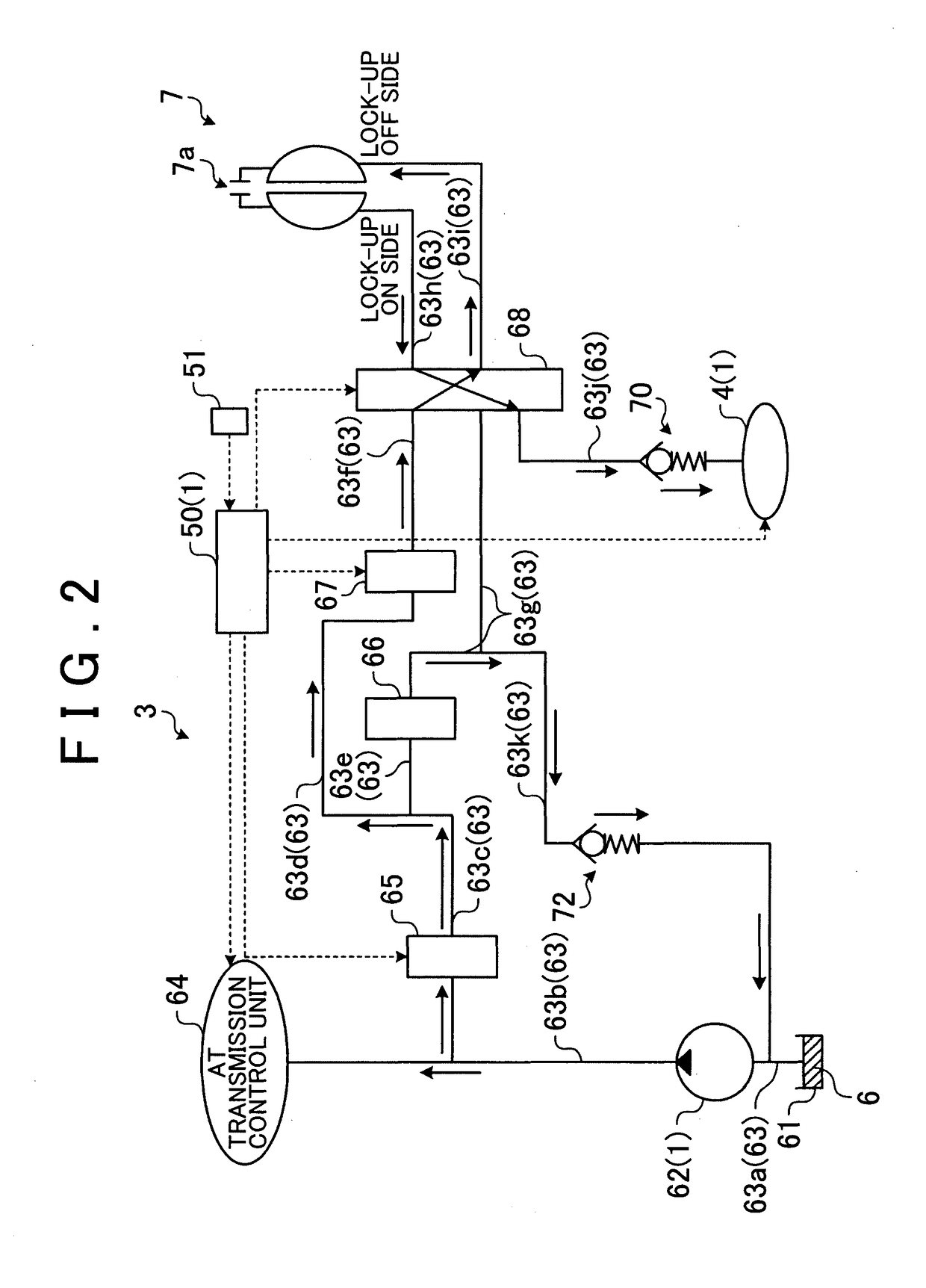
[0028]A first embodiment will be described with reference to FIGS. 1 to 10. This embodiment relates to the lubrication control device. FIG. 1 is a diagram illustrating a transmission according to the first embodiment of the invention. FIG. 2 is a diagram illustrating the flow of oil in a lock-up clutch released state according to the first embodiment. FIG. 3 is a diagram illustrating the flow of oil in a lock-up clutch engagement state according to the first embodiment. FIG. 4 is a schematic configuration diagram of the lubrication control device according to the first embodiment. FIG. 5 is a diagram illustrating a heat exchange amount of a heat exchanger. FIG. 6 is a diagram illustrating a temperature increment in the heat exchanger. FIG. 7 is a diagram illustrating a relationship between a T / M oil temperature and the opening degree of an oil quantity control valve. FIG. 8 is an explanatory drawing of a lubrication state. FIG. 9 is an explanatory drawing of a lower limit flow rate ...
second embodiment
[0080]A second embodiment will be described with reference to FIGS. 11 and 12. In the following description of the second embodiment, the same reference numerals will be used to refer to components that have similar functions to those in the description of the first embodiment and description thereof will be omitted. FIG. 11 is a diagram illustrating a map of the opening degree of an oil quantity control valve according to the second embodiment and FIG. 12 is a diagram illustrating a relationship between a throttle opening degree and the opening degree θ of the oil quantity control valve pertaining to a case where the T / M oil temperature is constant. The second embodiment differs from the first embodiment in that the opening degree command value θcom for the oil quantity control valve 41 is changed based on the throttle opening degree as well as the temperature of the transmission oil 6.
[0081]As illustrated in FIG. 11, the opening degree θ of the oil quantity control valve 41 (requi...
first modification example
of Each Embodiment
[0095]A first modification example of the first embodiment and the second embodiment will be described. In the first embodiment and the second embodiment, the liquid-phase medium that exchanges heat with the transmission oil 6 in the heat exchanger 42 is the engine oil 5. Instead, however, heat exchange may be carried out between the transmission oil 6 and the coolant 9 in the heat exchanger 42. Alternatively, both the heat exchange between the transmission oil 6 and the engine oil 5 and the heat exchange between the transmission oil 6 and the coolant 9 may be carried out in the heat exchanger 42.
[0096]In a case where the heat exchanger 42 performs heat exchange between the transmission oil 6 and the coolant 9 and the T / M oil temperature is high, the transmission oil 6 is cooled by the coolant 9. In the lubrication control device 1 according to each embodiment described above, the cooling performance in cooling the transmission oil 6 is improved since the supply oi...
PUM
 Abstract
Description
Claims
Application Information
 - R&D
- Intellectual Property
- Life Sciences
- Materials
- Tech Scout
- Unparalleled Data Quality
- Higher Quality Content
- 60% Fewer Hallucinations
Browse by: Latest US Patents, China's latest patents, Technical Efficacy Thesaurus, Application Domain, Technology Topic, Popular Technical Reports.
© 2025 PatSnap. All rights reserved.Legal|Privacy policy|Modern Slavery Act Transparency Statement|Sitemap|About US| Contact US: help@patsnap.com


