Vision algorithm performance using low level sensor fusion

a technology of low-level sensor and vision algorithm, which is applied in the field of vision algorithm performance using low-level sensor fusion, can solve the problems of limited work in the field of low-level sensor fusion, and achieve the effects of improving the classification results, and reducing false detections

Inactive Publication Date: 2017-08-24
APTIV TECH LTD
View PDF2 Cites 25 Cited by
  • Summary
  • Abstract
  • Description
  • Claims
  • Application Information

AI Technical Summary

Benefits of technology

[0010]In one exemplary embodiment of the present invention, a range map is determined from Radar (LiDAR) detection range information. The range map can be used by vision algorithms to decide on the scale of search to use, on determining Time To Contact (TTC), and for properly placing vision detection boxes on the ground.
[0011]In an alternative embodiment of the present invention, the speed of the object in the image is determined from RDU range rate information. This help vision tracking by limiti

Problems solved by technology

There is limited work in the a

Method used


Image

  • Vision algorithm performance using low level sensor fusion
  • Vision algorithm performance using low level sensor fusion
  • Vision algorithm performance using low level sensor fusion

Examples


Embodiment Construction

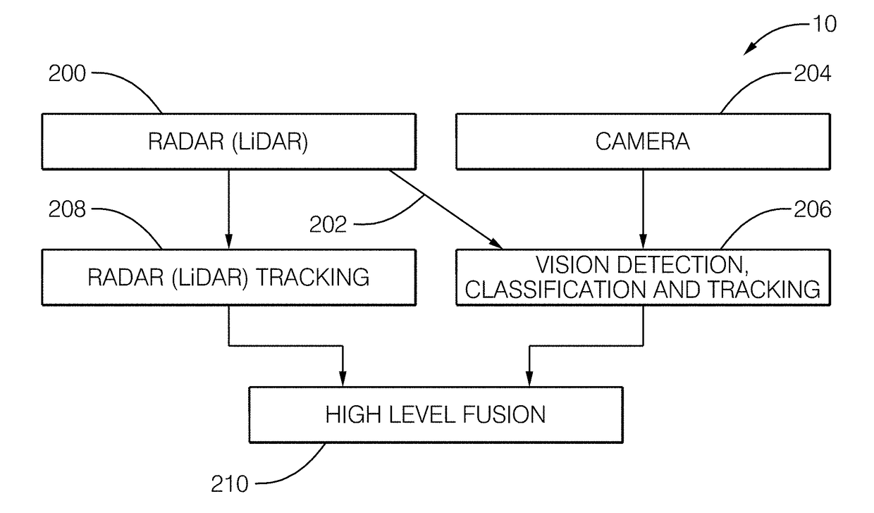
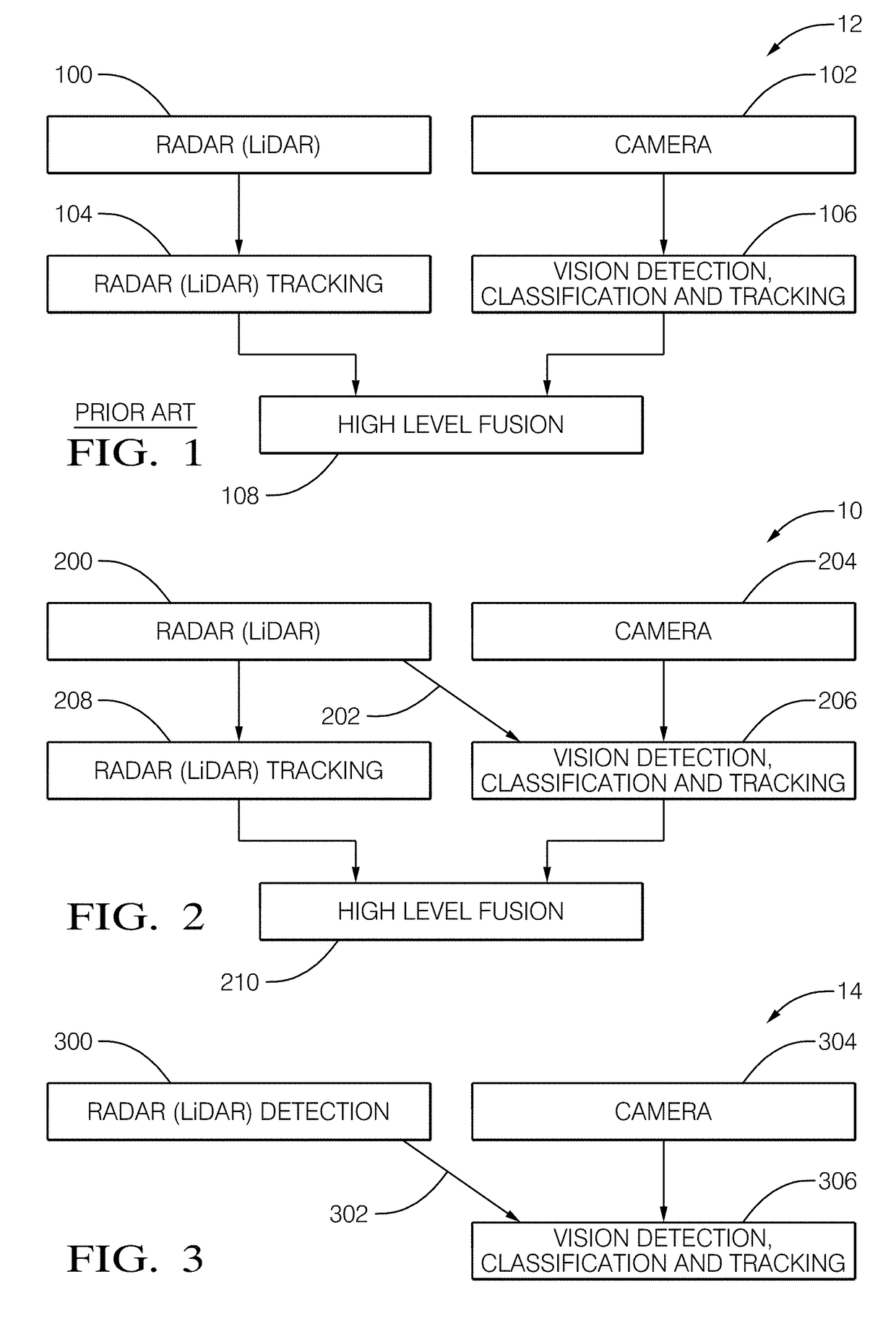
[0025]The present principles advantageously provide a method and system for improving vision detection, classification and tracking based on RDUs. Although the present principles will be described primarily within the context of using Radar (LiDAR), the specific embodiments of the present invention should not be treated as limiting in the scope of the invention. For example, in an alternative embodiment of the present invention, a Light Emitting Diode (LED) sensor may be used.

[0026]In ADAS and automated driving systems, sensors are used to detect, classify, and track obstacles around the host vehicle. Objects can be Vehicles, Pedestrian, or unknown class referred to as general objects. Typically two or more sensors are used to overcome the shortcoming of single sensor and to increase the reliability of object detection, classifications, and tracking. The output of the sensors are then fused to determine the list of objects in the scene. Fusion can be done at a high level where every...


PUM


Abstract

A method and system that performs low level fusion of Radar or LiDAR data with an image from a camera. The system includes a radar-sensor, a camera, and a controller. The radar-sensor is used to detect a radar-signal reflected by an object in a radar-field-of-view. The camera is used to capture an image of the object in a camera-field-of-view that overlaps the radar-field of view. The controller is in communication with the radar-sensor and the camera. The controller is configured to determine a location of a radar-detection in the image indicated by the radar-signal, determine a parametric-curve of the image based on the radar detections, define a region-of-interest of the image based on the parametric-curve derived from the radar-detection, and process the region-of-interest of the image to determine an identity of the object. The region-of-interest may be a subset of the camera-field-of-view.

Description

TECHNICAL FIELD OF INVENTION[0001]Described herein are techniques for fusing Radar / LiDAR information with camera information to improve vision algorithm performance. The approach uses low level fusion where raw active sensor information (detection, range, range-rate, and angle) are sent to the vision processing stage. The approach takes advantage of active sensor information early in vision processing. The disclosure is directed to Advanced Driver Assistance Systems (ADAS) and autonomous vehicles. In these systems, multiple sensors are used to detect obstacles around the vehicle.BACKGROUND OF INVENTION[0002]Current ADAS and autonomous vehicle systems use multiple sensors to detect obstacles around the vehicle. Most fusion systems use high level fusion as shown in the FIG. 1. In the figure, Radar 100 generates Radar Detection unit (RDUs), and a camera 102 generates an image. Each sensor then processes the information 104, 106 independently. The information from each sensor is then me...

Claims


Application Information

Patent Timeline
IPC IPC(8): G01S13/86G01S17/93G01S13/93G01S17/02G01S13/931G01S17/86G01S17/931
CPCG01S13/867G01S17/023G01S2013/9367G01S13/931G01S17/936G06V20/58G01S17/66G01S13/726G01S2013/9323G01S2013/93271G01S17/931G01S17/86
Inventor IZZAT, IZZAT H.MV, ROHITH
Owner APTIV TECH LTD
Why Eureka
Try Eureka