Method for analyzing a sample with a non-linear microscopy technique and non-linear microscope associated

a microscopy and sample technology, applied in the direction of instruments, optical elements, fluorescence/phosphorescence, etc., can solve the problems of weak light power, weak light power, and limited versatility of this approach, and achieve the effect of high speed

Active Publication Date: 2017-08-24
INST NAT DE LA SANTE & DE LA RECHERCHE MEDICALE (INSERM) +2
View PDF1 Cites 11 Cited by
  • Summary
  • Abstract
  • Description
  • Claims
  • Application Information

AI Technical Summary

Benefits of technology

[0011]The invention aims at solving the problems of the known systems with a new system for generating a light pattern (three-dimension scans and spatially extended light patterns), which is able to operate at a high speed.

Problems solved by technology

However, due to the poor spatio-temporal patterning capacity of both galvanometers and mechanical Z-scanning devices, the versatility of this approach is limited.
Such devices are also limited in their ability to refresh at high rate the modulation pattern, in most of the cases in the range of a few Hertz (Hz) to a few kilohertz (kHz).
The system described in the Reddy et al. article, which contains four acousto-optical deflectors, implies strong loss of light power because the diffraction efficiency in an acousto-optic deflector is limited even in its optimal configuration.
In addition, the third and the fourth acousto-optic deflectors of the system cannot be used in their optimal configuration (Bragg incidence), which also contributes to increased loss of light power in the system.
Finally, the linear frequency chirps have to be stopped each time they reach the limit of the frequency bandwidth of the acousto-optical deflector, thus limiting the dwell time on the points accessed in three dimensions and the useful fraction of the duty cycle.
Finally, such system is limited to the scanning in three dimensions of a single spot and cannot be used to create spatially extended light patterns.

Method used


Image

  • Method for analyzing a sample with a non-linear microscopy technique and non-linear microscope associated
  • Method for analyzing a sample with a non-linear microscopy technique and non-linear microscope associated
  • Method for analyzing a sample with a non-linear microscopy technique and non-linear microscope associated

Examples


Embodiment Construction

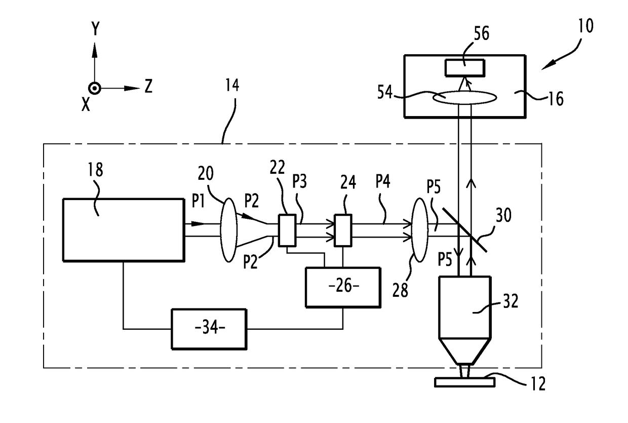
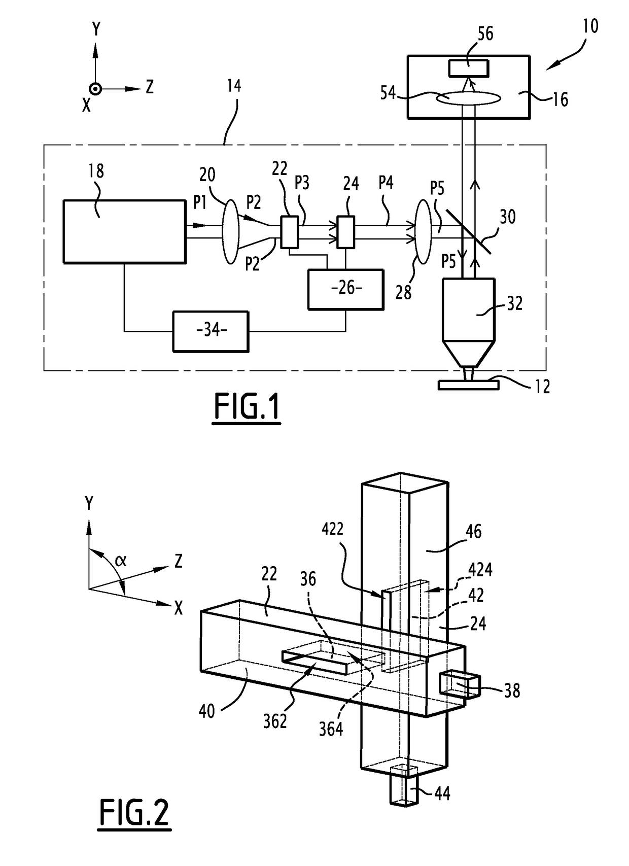
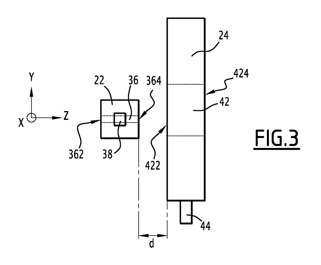
[0055]For the remainder of the description, a longitudinal direction is defined: the longitudinal direction corresponds to the general direction of the propagation of light. Two transversal directions perpendicular to the longitudinal direction are also defined, the first transversal direction being further perpendicular to the second transversal direction. The longitudinal and transversal directions are respectively symbolized by an axis Z and axes X and Y on FIGS. 1 to 3.

[0056]A two-photon microscope 10 adapted to achieve a two-photon microscopy on a sample 12 is represented on FIG. 1.

[0057]Alternatively, the microscope 10 may be any microscope able to achieve a non-linear microscopy technique. Such microscope is called a non-linear microscope.

[0058]The sample 12 is, for instance, a soft tissue. In the meaning of the present invention, a soft tissue is an organic tissue, which can have an animal or vegetal origin. For instance, such a soft tissue can be a muscle or any portion of ...


PUM

PropertyMeasurementUnit
angleaaaaaaaaaa
angleaaaaaaaaaa
timeaaaaaaaaaa

Abstract

The present invention concerns a method for generating a pattern of light, this method comprising the following steps: a) emitting an input laser pulse (P1), b) deflecting the input laser pulse (P1) by a first deflector (22) to obtain a first laser pulse, c) deflecting the first laser pulse (P3) by a second deflector (24) to obtain a second laser pulse (P4), and d) focusing the pulse (P4) by an optical element characterized in that: —the first deflector (22) shapes the first laser pulse (P3) according to a first function, —the second deflector (24) shapes the second laser pulse (P4) according to a second function, and —the first function f(x) and the second function g(y) are computed and/or optimized to obtain the desired pattern of light.

Description

TECHNICAL FIELD OF THE INVENTION[0001]The invention relates to a method for analyzing or modifying a sample with a non-linear microscopy technique. The invention also concerns the non-linear microscope associated.BACKGROUND OF THE INVENTION[0002]In optical microscopy, the generation of patterns of light at high spatial and temporal resolution is desirable. In the present application, a pattern of light refers to the focusing of light at one or more spots at given positions in 2D and 3D and to the sculpting of the light intensity distribution in an extended pattern around these spots.[0003]A pattern of light can be used to image the structure and activity of biological samples, such as neuronal dendrites. A pattern of light also enables to modify optically the biological activity or chemical environment of these biological samples. It is therefore desirable to be able to generate arbitrary light patterns at a high speed.[0004]For this, it is known to carry out a three-dimensional sca...

Claims


Application Information

Patent Timeline
Patent Type & Authority Applications(United States)
IPC IPC(8): G02B21/16G02F1/11G01N21/64G02B21/00G02F1/33G03H1/00
CPCG02B21/16G02F1/33G03H1/0005G02B2207/114G02B21/0036G02F1/113G03H2001/005G01N21/6458G02B21/0076G02B26/101G02B26/106
Inventor LEGER, JEAN-FRANCOISBOURDIEU, LAURNETDIEUDONNE, STEPHANE
Owner INST NAT DE LA SANTE & DE LA RECHERCHE MEDICALE (INSERM)
Why Eureka
Try Eureka