Pneumatic or hydraulically operated linear driver

a linear driver and pneumatic or hydraulic technology, applied in the field of linear drivers, can solve the problems of significant risk to the safety of workers involved in the formation of the required pile, the formation of the hole in which the pile necessarily sits, and the provision of cast-in-situ piles unsuitable for a number of applications, so as to reduce noise and minimise the weight of the driver

Inactive Publication Date: 2017-08-31
ECOSMART LTD
View PDF11 Cites 5 Cited by
  • Summary
  • Abstract
  • Description
  • Claims
  • Application Information

AI Technical Summary

Benefits of technology

[0018]The driver may further comprise a housing, surrounding and slidably connected to the driving member, which comprises means for attaching the driver to a support structure. Due to the reduced noise generated by the driver of embodiments of the present invention, the housing need not be acoustically sealed, and may be an open sided housing such as a cage to minimise weight of the driver.
[0019]The driver may further comprise an actuator to provide a signal to close the valve arrangement before the weighted sleeve impacts the driving member. The actuator may comprise an actuator rod which is depressed by the weighted sleeve as it moves in the second direction. Engagement of the sleeve with the actuator rod shortly before impact with the elements of the driving member would provide a simple means for ensuring correct timing of the valve closure.

Problems solved by technology

One of the challenges faced during the provision of cast-in-situ piles is the formation of the hole in which the pile necessarily sits.
There are, however, several disadvantages associated with such methods.
Furthermore, the length of a pile former used to reach the required depth in the ground often necessitates the use of large support structures and associated equipment, which can be expensive, time consuming to mobilise, and which may pose a significant risk to the safety of workers involved in the formation of the required pile.
These disadvantages in general make the provision of cast-in-situ piles unsuitable for a number of applications, and thus cast-in-situ piles are generally used only in large scale, or large load-bearing, construction projects.
A further disadvantage arising from the need to impart a large amount of energy to the pile formers is the large amount of noise and disruption that pile driving generally creates.
Each impact generates a large amount of noise, which is particularly undesirable if construction is taking place in already built-up areas, eg close to existing residences or office buildings.
Diesel hammers thus avoid the physical impacts between the weight and the pile former, but the combustion events mean that they are typically even louder in operation than percussive hammers, so do not overcome this shortcoming.
One major drawback with vibratory pile driving is that soil conditions and the installation procedure can greatly affect the bearing capacity of vibrated piles, so the method is only suitable for use with certain soil types, and even then the bearing capacity of vibratory driven piles is difficult to predict with any degree of certainty.
In addition, the intensity of ground vibrations generated can be problematic, and it is extremely important to avoid resonance in the ground or at adjacent structures or structural elements.
The method is also relatively costly as it requires special equipment.

Method used


Image

  • Pneumatic or hydraulically operated linear driver
  • Pneumatic or hydraulically operated linear driver
  • Pneumatic or hydraulically operated linear driver

Examples


Embodiment Construction

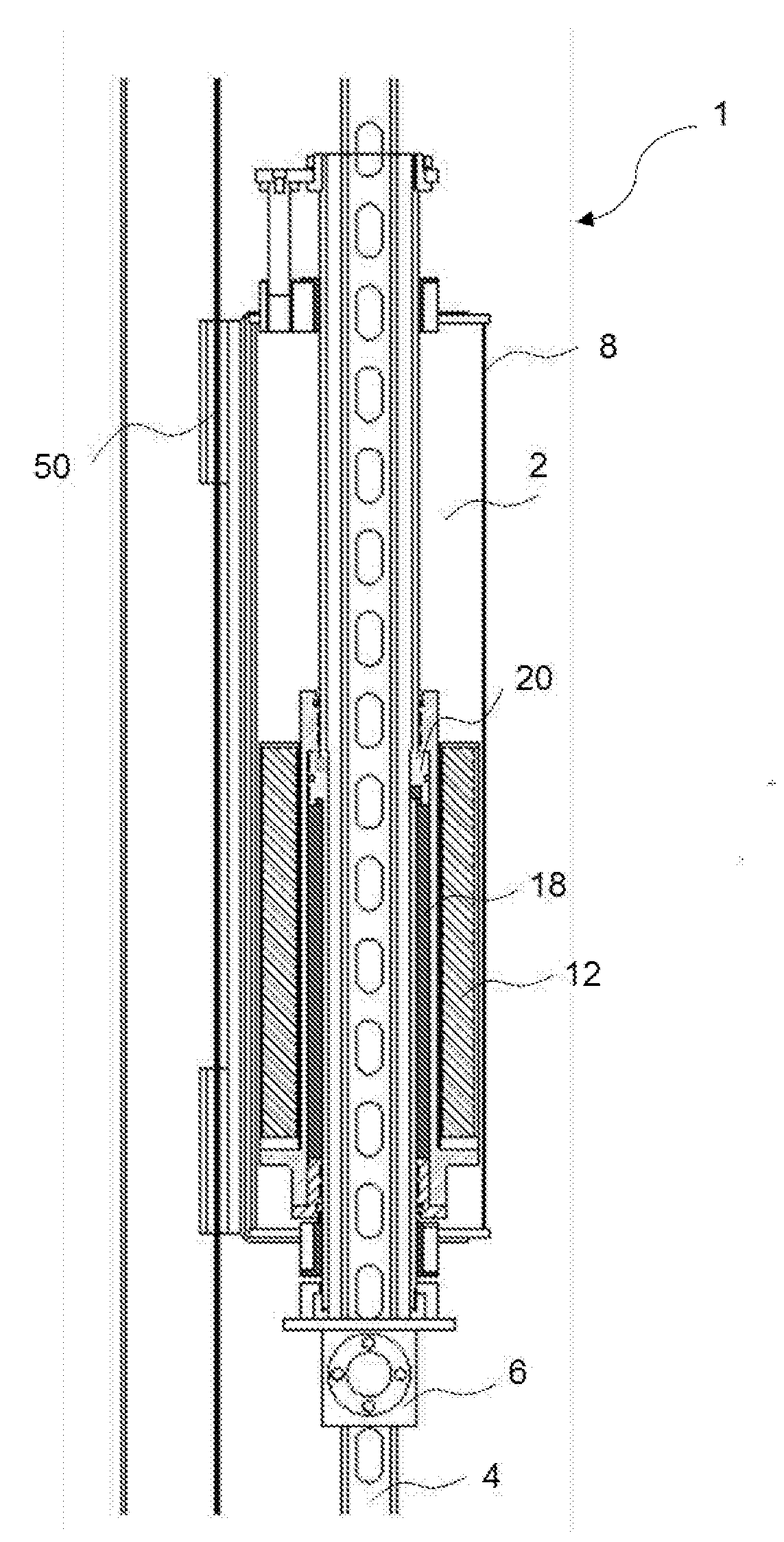
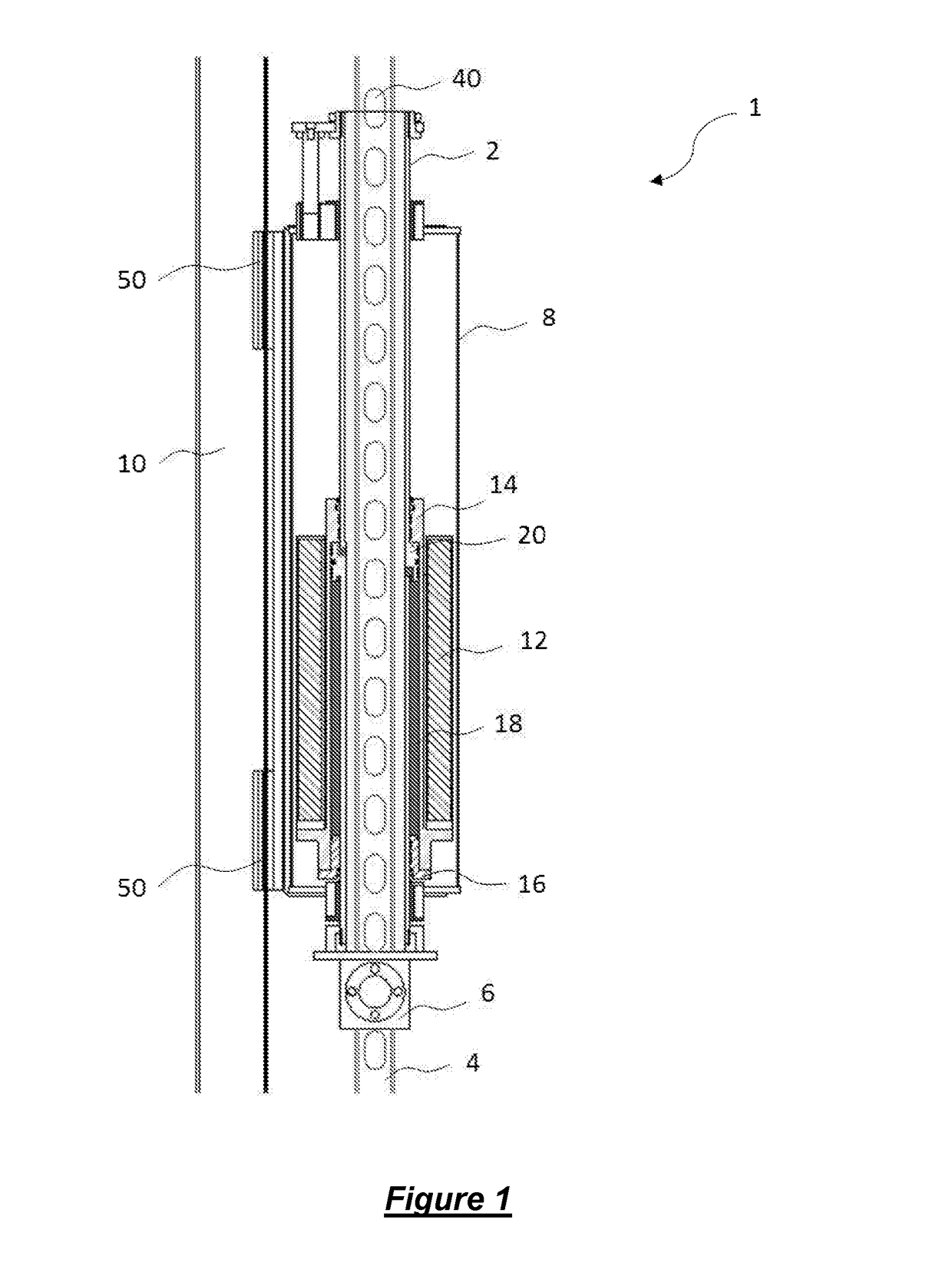
[0055]A first embodiment of a pile driver according to the present invention, in the form of a pile driver 1, is shown in FIG. 1.

[0056]The pile driver 1 comprises a driving tube 2 which is shown located around a pile former 4 and attached thereto by a clamp 6 at its lower end. A cage 8 is slidably mounted to the driving tube and provides a means for attaching the pile driver to a mast 10 or other supporting fixture. Typically, piling hammers have to incorporate a housing that is fully sealed to attenuate airborne noise. Such housings are heavy, which increases the overall weight of the hammer. The quieter operation of the driver according to embodiments of the invention avoids the need for such housings, so that a simpler, lighter housing, for example a cage type housing, can be used.

[0057]A weighted sleeve 12 is located around the driving tube 2 and within the cage 8. Both end portions 14,16 of the weighted sleeve 12 are in sealing contact with an outer surface of the driving tube ...


PUM


Abstract

A linear driver is provided and particularly, but not exclusively, to a linear driver for use in the field of civil engineering or construction, for example in the formation of piles or piers as foundations. The driver includes a weighted sleeve slidable relative a driving member, and a valve arrangement to control the linear movement of the weighted sleeve relative to the driving member. Closing the valve arrangement serves to stop movement of the weighted sleeve and transfer momentum to the driving member without physical impact between the weighted sleeve and the driving member.

Description

CROSS-REFERENCE TO RELATED APPLICATIONS[0001]This application claims priority to PCT Application No. PCT / GB2015 / 052389, having a filing date of Aug. 17, 2015, based off of GB Application No. 1414554.4 having a filing date of Aug. 15, 2014, the entire contents of which are hereby incorporated by reference.FIELD OF TECHNOLOGY[0002]The following relates to a linear driver and particularly, but not exclusively, to a linear driver for use in the field of civil engineering or construction, for example in the formation of piles or piers as foundations.BACKGROUND[0003]It is conventional to provide a foundation as the lowest supporting layer of a structure to be built or else to shore up the ground. In general, foundations can be split into two different categories, so-called shallow foundations and deep foundations, with the only real difference between the two categories of foundation being the depth to which they are embedded in the ground.[0004]A well-known form of deep foundation is a s...

Claims


Application Information

Patent Timeline
Patent Type & Authority Applications(United States)
IPC IPC(8): E02D7/06E02D5/22E02F9/22E02D7/14E02D7/16E02F3/32
CPCE02D7/06E02D7/16E02F3/32E02D5/22E02D7/14E02F9/2267E02F9/2271
Inventor HICKSON, PETER M.
Owner ECOSMART LTD
Why Eureka
Try Eureka