Method and Apparatus for Joining Workpieces at a Lap Joint

a technology of lap joints and workpieces, which is applied in the direction of laser beam welding apparatus, welding/soldering/cutting articles, manufacturing tools, etc., can solve the problems of increasing the number of lap joints, so as to reduce the effort for part preparation and high degree of automation. , the effect of constant high quality of the weld seam

Inactive Publication Date: 2017-09-14
SCANSONIC MI
View PDF8 Cites 13 Cited by
  • Summary
  • Abstract
  • Description
  • Claims
  • Application Information

AI Technical Summary

Benefits of technology

[0045]The advantage of the method according to the invention is that a gap, which is formed at the lap joint and has a discontinuous elevation changing in random manner along the joint, can always be closed reliably, continuously and in real-time by means of a purpose-oriented adaptation of the process parameter (such as, for example, oscillation frequency or amplitude). Since the process parameter to be applied during the welding process are continuously determined anew on the basis of the actual situation detected by means of the sensor systems, their adaptation can be carried out dynamically during the process, wherein—immanent to the process—acting to changing input parameter (such as positional changes of the workpieces relative to each other at the weld seam) is also possible in real time.
[0046]Another advantage of the method according to the invention is its high degree in automatization, such that only at the beginning of the welding process a (manual) input of values influencing the

Problems solved by technology

Changes in the weld seam path (gap between the workpieces at the joint, changed speed of the relative movement and heat dissipation), however, cause changes in the size of the weld pool.
The vapor capillary also affects the quality of the weld.
This problem in particular holds for the high-strength steel materials, which are becoming more and more widespread.
In the subsequent joining stations, the gaps resulting from the positioning of the high-strength workpieces cannot be eliminated even when applying high contact pressure forces.
A further aggravating aspect concerns the heat introduced into the components by the joining process, which leads to a heat distortion.
In the cold state the components may have a zero gap while only during introduction of heat a gap arises which is invisible to the production and therefore cannot be compensated.
In particular, highly automated operation may result in undefined gaps.
By applying additional material, however, long cycle times are involved, which slows down the process significantly.
This in turn contradicts efficient mass production

Method used


Image

  • Method and Apparatus for Joining Workpieces at a Lap Joint
  • Method and Apparatus for Joining Workpieces at a Lap Joint
  • Method and Apparatus for Joining Workpieces at a Lap Joint

Examples


Embodiment Construction

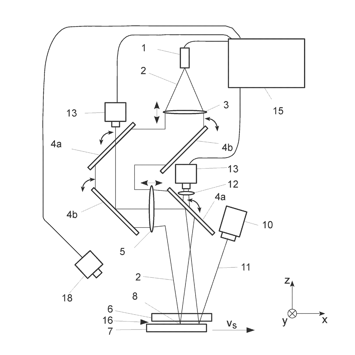
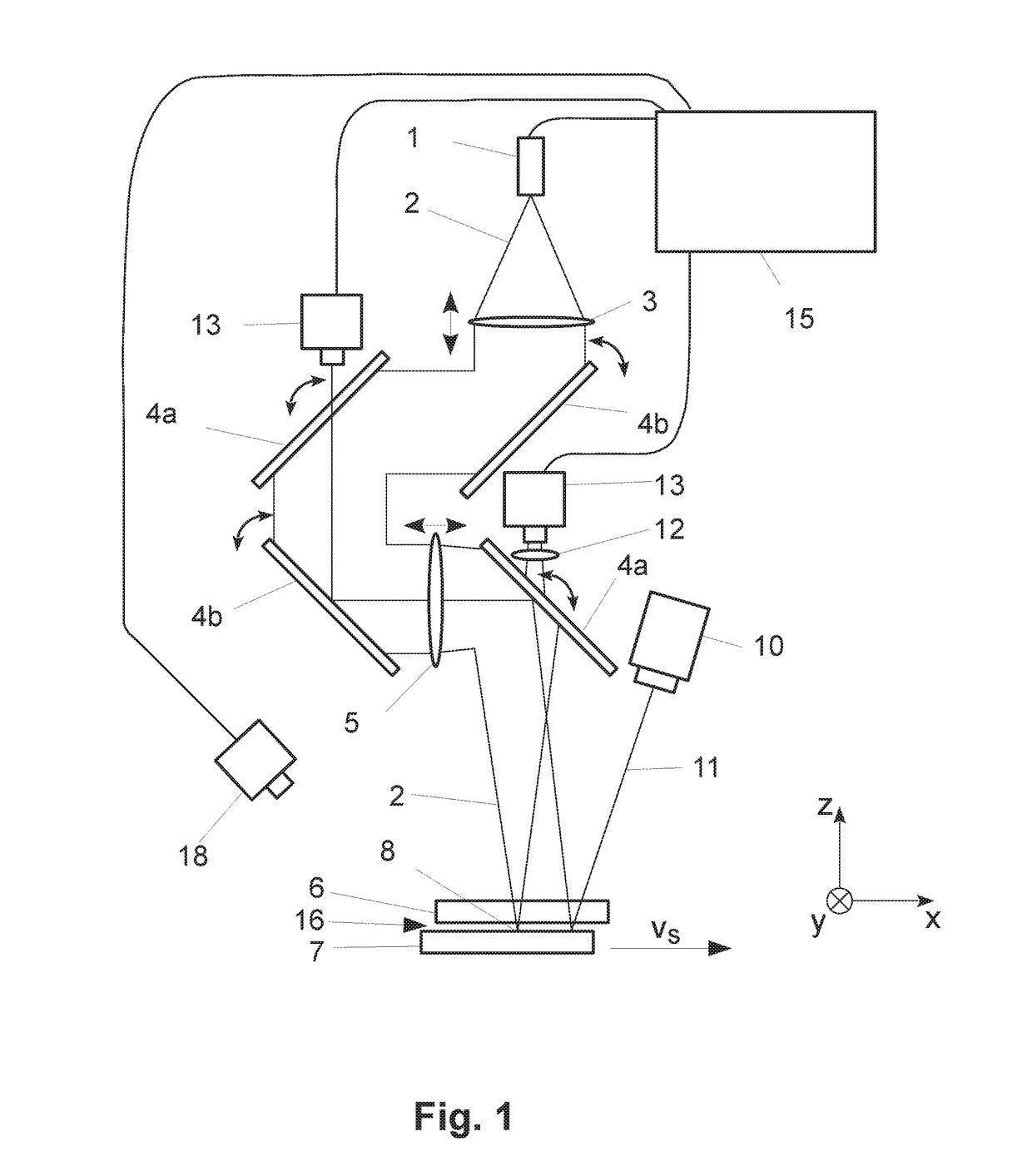
[0019]In accordance with the invention, the method and the joining apparatus for joining a plurality of workpieces, especially those made of aluminum or high-strength steel, at a lap joint by means of a processing beam are provided. The workpieces to be joined may be e. g. sheets of aluminum. The processing beam may be e.g. a laser beam; however, it may also be provided that the processing beam generally is a beam of electro-magnetic radiation (e.g. an infra-red beam), a particle beam (e.g. an electron beam) or a sound beam (e.g. in the form of directed ultrasound).

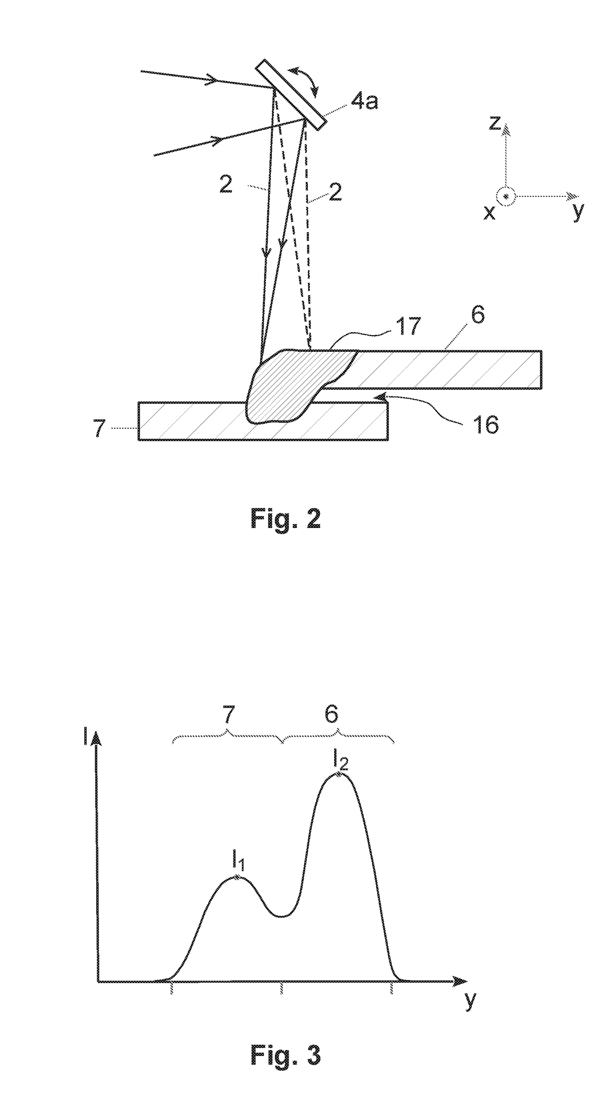
[0020]According to the invention the compensation of a gap formed between two workpieces at a lap joint is performed by melting of material from the upper sheet, i.e. the sheet metal respectively the workpiece arranged at the upper position (with respect to the plumb line) at the lap joint during joining, using the processing beam in such a way that the gap present at the joint is filled completely with molten material fl...


PUM

PropertyMeasurementUnit
Angleaaaaaaaaaa
Angleaaaaaaaaaa
Heightaaaaaaaaaa

Abstract

A method and an apparatus for joining two workpieces by means of a processing beam by forming a weld seam along a lap joint, wherein a gap formed at the lap joint between the two workpieces is filled during welding. The processing beam performs a spatial oscillatory movement parallel and/or perpendicular to the joint during welding. The oscillation parameters of said oscillation, the feed rate, the power of the processing beam and the angle of incidence of the processing beam onto the surfaces of the workpieces are adjusted dynamically during the welding process such that the upper sheet is fused in line with demand and the melt flows from the upper sheet down to the lower sheet thus closing the gap. The gap height is measured permanently during welding and the process parameters are adjusted such that a reliable closing of the gap is made possible.

Description

CROSS REFERENCE TO RELATED APPLICATIONS[0001]This application is the U.S. national stage of International Application No. PCT / DE2015 / 100496,filed on 2015-11-23. The international application claims the priority of DE 102014117157.8filed on 2014-11-24; all applications are incorporated by reference herein in their entirety.BACKGROUND[0002]1. Field of the Disclosure[0003]The invention relates to a method for joining a first and a second workpiece of a similar material, in particular of aluminum or a high-strength steel material, or of workpieces of dissimilar metallic materials to a component by means of a continuously emitting processing beam by forming a weld seam along a lap joint. By filling a gap formed between the workpieces at the lap joint, the weld seam quality is improved. The invention also relates to an apparatus for joining workpieces by forming a weld along a lap joint.[0004]2. Description of the Related Art[0005]During the welding process by means of a processing beam, ...

Claims


Application Information

Patent Timeline
IPC IPC(8): B23K26/044B23K26/242B23K31/12B23K26/03B23K26/082B23K26/046
CPCB23K26/044B23K26/082B23K26/046B23K31/125B23K2203/18B23K26/242B23K2203/04B23K2203/10B23K26/032B23K26/048B23K2103/04B23K2103/10B23K2103/18
Inventor ALBERT, FLORIANFIXEMER, PETERHASCHKE, IGORMULLER, ALEXANDERSIEVI, PRAVIN
Owner SCANSONIC MI
Why Eureka
Try Eureka