
Transmission coil for the inductive transfer of energy

a technology of inductive transfer and transmission coil, which is applied in the direction of transformer/inductance magnetic core, charging station, transportation and packaging, etc., can solve the problems of multiplication of separate components, and achieve the effect of reducing the expenditure of insulation and shielding, facilitating cooling, and significantly reducing the resonant voltag

Active Publication Date: 2017-09-14
ROBERT BOSCH GMBH
View PDF6 Cites 12 Cited by
  • Summary
  • Abstract
  • Description
  • Claims
  • Application Information

AI Technical Summary

Benefits of technology

This invention is about a new design for a mobile unit's transmission coil that is integrally connected to a power electronics module. This design reduces the size and weight of the coil, while also eliminating redundancy among components and saving material and installation costs. The coil arrangement is made up of concentric circles or a spiral path on the carrier, which shields the alternating magnetic fields to eliminate interference with radio transmissions and other electronic devices. The carrier also has ducts running through it for cooling, which helps to prevent overheating of the coil. This design helps to achieve a more compact and efficient transmission coil for use in mobile units.

Problems solved by technology

A disadvantage of the prior art is that in addition to the transmission coils a multiplicity of separate components are also required.

Method used


Image

  • Transmission coil for the inductive transfer of energy
  • Transmission coil for the inductive transfer of energy
  • Transmission coil for the inductive transfer of energy

Examples


Embodiment Construction

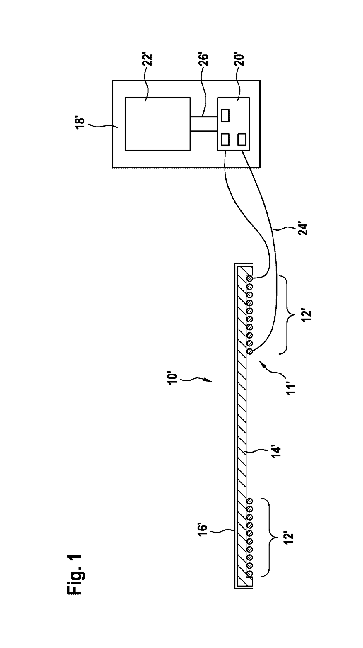
[0036]FIG. 1 shows a charging station with a transmission coil according to the prior art in a schematic illustration in a cross section from the side.

[0037]FIG. 1 illustrates a transmission coil 10′ which comprises a coil arrangement 11′ with a multiplicity of turns 12′. A ferrite element 14′, which serves as a ferromagnetic core of the coil arrangement 11′, is arranged around the turns 12′. The coil arrangement 11′ is provided with an electrically conductive shield (e.g. aluminum) 16′ in order to shield the magnetic stray field.

[0038]In order to generate a magnetic field, the coil arrangement 11′ is connected to a switching cabinet 18′ via a connecting line 24′. The switching cabinet 18′ comprises power electronics 20′ and a capacitor 22′. The capacitor 22′ is connected to the coil arrangement 11′ via a further connecting line 26′, the power electronics 20′ and the connecting line 24′, wherein the coil arrangement 11′ and the capacitor 22′ together form an oscillatory circuit.

[003...


PUM


Abstract

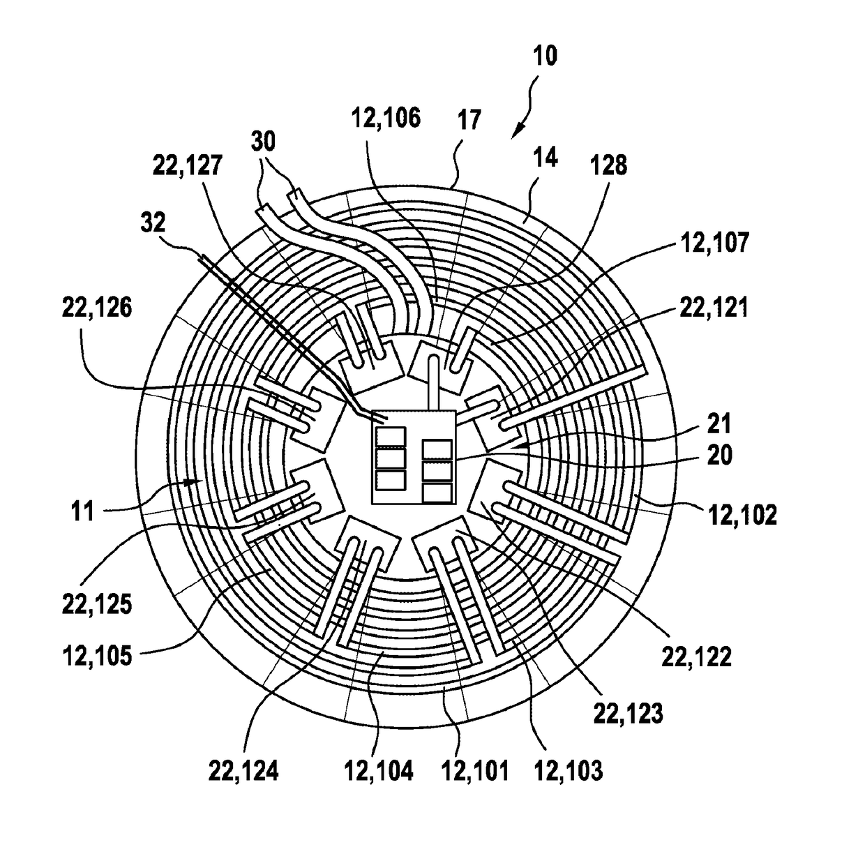
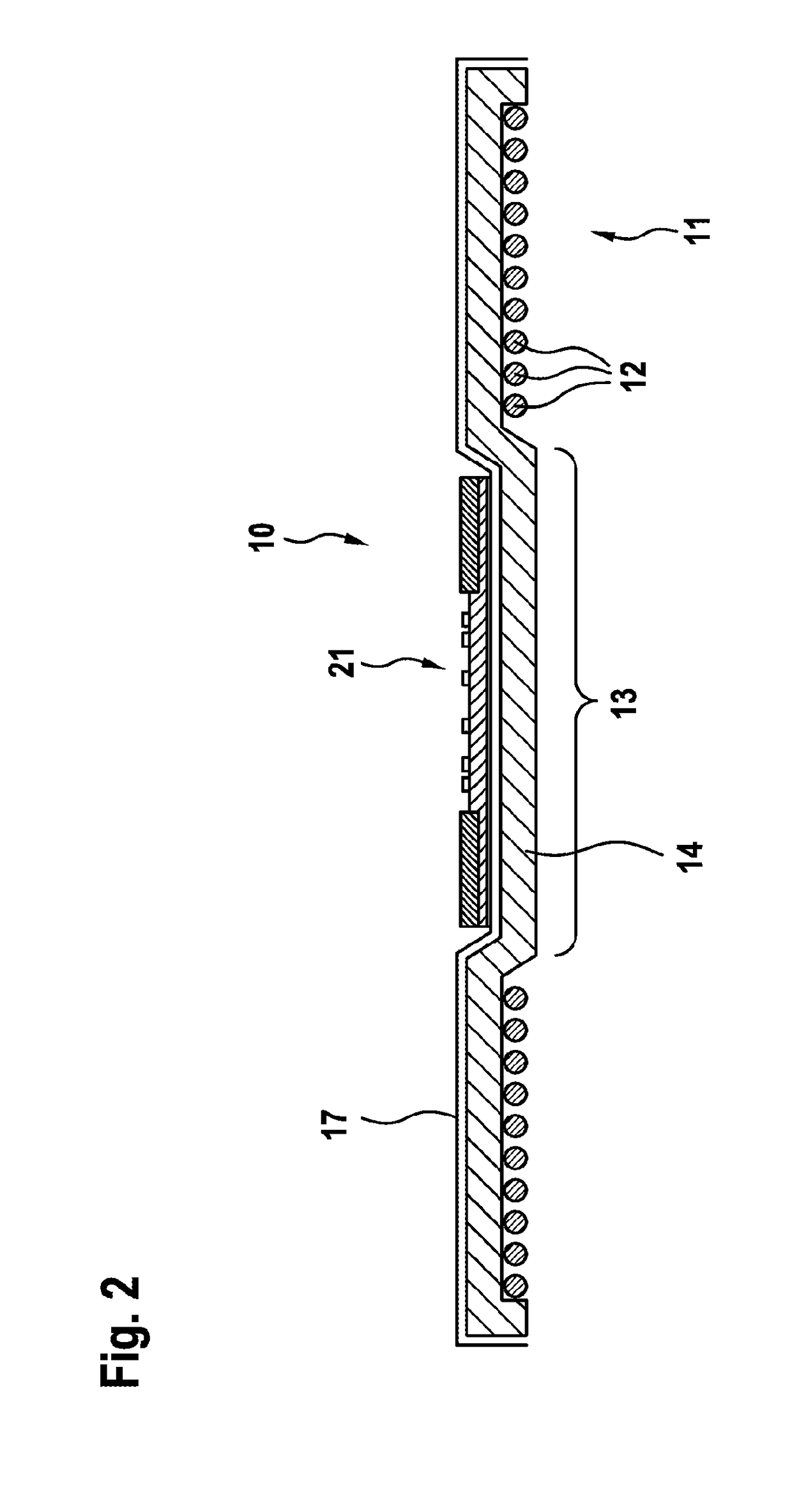
The invention relates to a transmission coil (10) configured for inductive energy transfer, comprising a carrier (17), a coil arrangement (11) having a plurality of turns (12), and a capacitance. It is thereby provided that the capacitance is formed of a plurality of capacitors (22), wherein each capacitor (22) is assigned to an individual turn (12) or to a group of at least two turns (12) of the coil arrangement (11), and together with the coil arrangement, the capacitors (22) are arranged on the carrier (17). The invention further relates to a stationary charging station and to a vehicle, each comprising such a transmission coil (10), and to a system for the inductive charging of vehicles. No drawing text to be translated

Description

BACKGROUND OF THE INVENTION[0001]The invention relates to a transmission coil which is configured to inductively transfer energy, comprising a carrier, a coil arrangement with a multiplicity of turns, and a capacitance which forms, together with the coil arrangement, an oscillatory circuit. Further aspects of the invention relate to a fixed charging station and to a vehicle, each comprising such a transmission coil, and to a system for inductively charging vehicles comprising a fixed charging station and a vehicle.[0002]Various systems for the contactless transfer of energy are known for conveniently charging electrical energy stores. Depending on the configuration, these systems can be used, for example, for charging consumer electronics such as, for example, cell phones or MP3 players or for charging electrically driven vehicles. Electrically driven vehicles comprise, for example, industrial trucks which are used for transporting goods in a warehouse, hybrid vehicles which have bo...

Claims


Application Information

Patent Timeline
IPC IPC(8): B60L11/18H01F27/24H01F27/28H02J50/12H02J7/02H02J7/00
CPCB60L11/1825B60L11/182H02J7/025H02J7/0027H01F27/24H02J50/12H01F27/2876H01F27/288H01F27/28H02J5/005H01F27/40H01F38/14H01F27/36H01F27/363Y02T90/14B60L53/12B60L53/31B60L53/302H02J2310/48H02J50/005Y02T10/7072Y02T90/12Y02T10/70
Inventor STEWING, FELIXDIEKHANS, TOBIAS
Owner ROBERT BOSCH GMBH
Learn More