Motorized window treatment
a motorized and window treatment technology, applied in the direction of door/window protective devices, power management, etc., can solve the problems of requiring subsequent repair, high cost of running additional ac main line voltage wiring to the electronic drive unit, and unsatisfactory aesthetics, etc., to achieve the effect of not expensive to replace, easy to clean, and easy to clean
- Summary
- Abstract
- Description
- Claims
- Application Information
AI Technical Summary
Benefits of technology
Problems solved by technology
Method used
Image
Examples
first embodiment
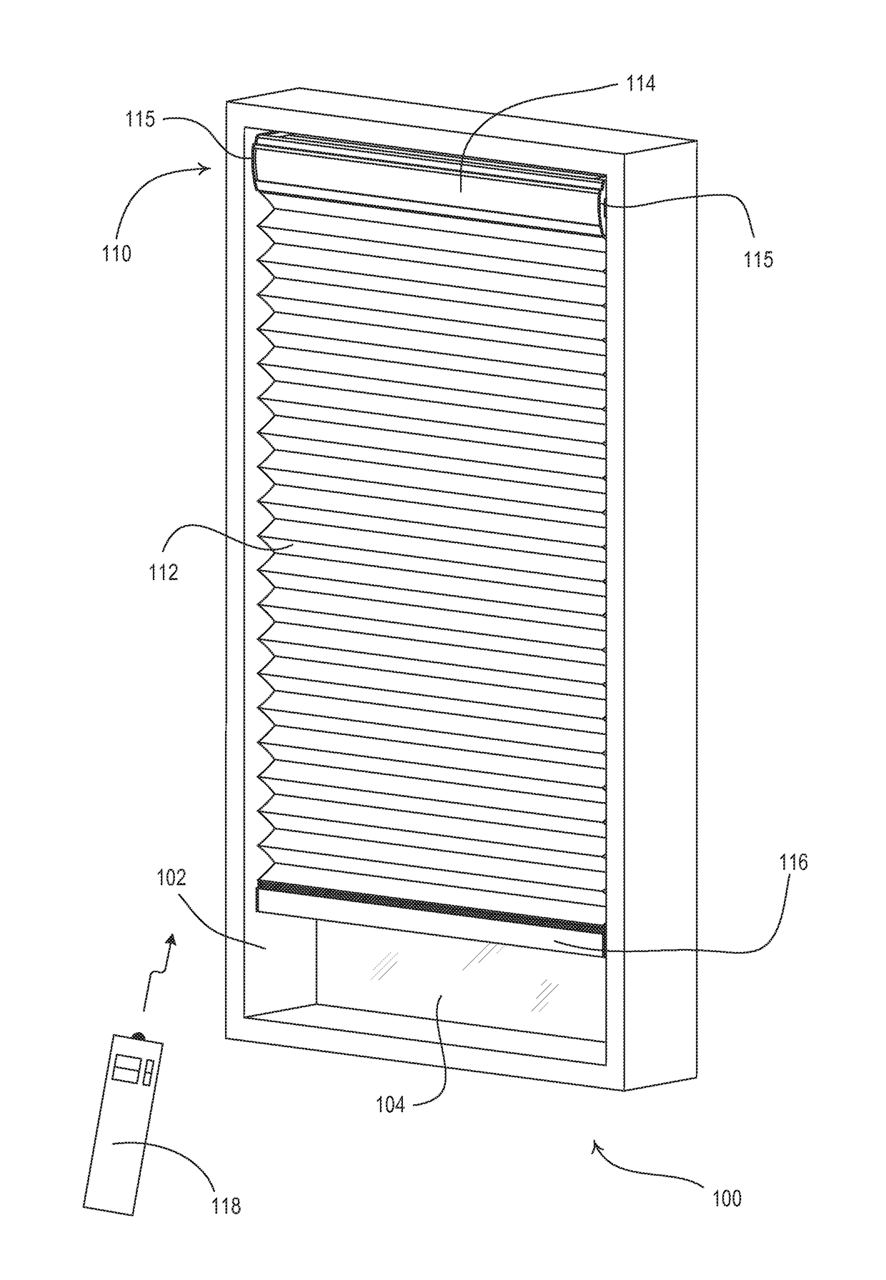
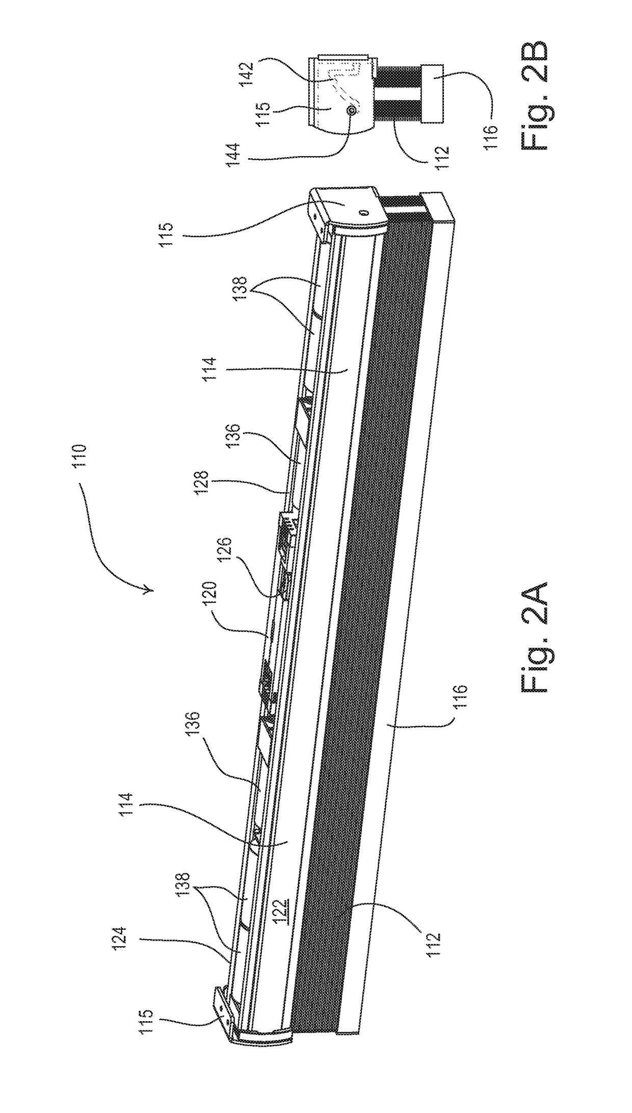
[0085]According to the present invention, the spring assist assemblies 135 are coupled to the drive shafts 132 with one of the spring assist assemblies housed in each of the lift cord spool enclosures 136 as shown in FIG. 3. Each spring assist assembly 135 includes a constant-force spring (not shown) having a first end attached to the respective lift cord spool enclosure 136 (which is fixedly attached to the head rail 114) and a second end attached to the respective drive shaft 132. The spring assist assemblies 135 operate to provide a constant torque (e.g., approximately 0.44 Newtons) on the drive shafts 132 in the direction opposite the direction of the torque provided on the drive shafts by the lift cords 130. For example, the constant amount of torque provided by the spring assist assemblies 135 may be approximately equal to the torque provided on the drive shafts 132 by the lift cords 130 when the weighting element 116 is positioned half-way between the fully-open position PFUL...
second embodiment
[0137]FIGS. 21A and 21B are partial perspective views of the motor drive unit 720 and the headrail 114 of the motorized window treatment 710 of the The antenna 768 is adapted to extend from the motor drive unit 720 and is received in an elongated antenna wire carrier 770. As shown in FIG. 21A, the antenna wire carrier 770 may be located in a first position immediately adjacent the motor drive unit 720 above the external side 124 of the headrail 114. The antenna wire carrier 770 may be removed from the first position and re-located into a second position in which the antenna 768 is slightly offset (e.g., by a distance of approximately 0.4 inch) from the motor drive unit 720 as shown in FIG. 21B. The antenna wire carrier 770 comprises clips 772 that are adapted to snap onto the top edge of the external side 124 of the headrail 114 in the second position. The antenna wire carrier 770 provides a mechanical means for adjusting the RF sensitivity of the RF receiver 766 and thus the power...
third embodiment
[0159]According to the present invention, one of the signal repeaters (e.g., signal repeater 1060A) operates as a “main” repeater (i.e., a main controller) to facilitate the operation of the load control system 1000. The main repeater 1060A has a database, which defines the operation of the load control system, stored in memory. For example, the main repeater 1060A is operable to determine which of the lighting load 1032 is energized and to use the database to control any visual indicators of the dimmer switch 1030 and the keypads 1042, 1040 accordingly to provide the appropriate feedback to the user of the load control system 1000. In addition, the control devices of the load control system may be operable to transmit status information to the signal repeaters 1060A, 1060B. For example, the motor drive unit 1020 of each of the motorized window treatments 1010 may be operable to transmit a digital message representative of the magnitude of the respective battery voltage to the signa...
PUM
 Abstract
Description
Claims
Application Information
 - R&D
- Intellectual Property
- Life Sciences
- Materials
- Tech Scout
- Unparalleled Data Quality
- Higher Quality Content
- 60% Fewer Hallucinations
Browse by: Latest US Patents, China's latest patents, Technical Efficacy Thesaurus, Application Domain, Technology Topic, Popular Technical Reports.
© 2025 PatSnap. All rights reserved.Legal|Privacy policy|Modern Slavery Act Transparency Statement|Sitemap|About US| Contact US: help@patsnap.com


