Motor, and motor control system

a technology of motor control and control system, which is applied in the direction of machines/engines, mechanical equipment, liquid fuel engines, etc., can solve the problems of affecting the operation of the motor, causing seizure, and increasing the contact friction torque of the dynamic pressure gas bearing, and causing the effect of causing seizur

Inactive Publication Date: 2017-09-21
COPAL ELECTRON CO LTD
View PDF0 Cites 7 Cited by
  • Summary
  • Abstract
  • Description
  • Claims
  • Application Information

AI Technical Summary

Benefits of technology

[0023]According to the motor control system of the eighth aspect, in addition to the effects exerted by any one of the fourth to seventh aspects, the control unit reduces the number of rotations of the motor after receiving the rotation detection signal until the rotation detection signal is not received any more. Thereby, the rotation of the auxiliary bearings is suppressed by the non-c

Problems solved by technology

Thus, when, due to an external disturbance or the like added to the motor, the shaft and the sleeve swing relatively in the direction in which the rotation axis of a rotating body is inclined and are brought into contact with each other, a contact friction torque of the dynamic pressure gas bearing is increased, and seizure is generated by adhesion or galling of the dynamic pressure gas bearing.
Thus, fatal damage could possibly be made to the dynamic

Method used


Image

  • Motor, and motor control system
  • Motor, and motor control system
  • Motor, and motor control system

Examples


first embodiment

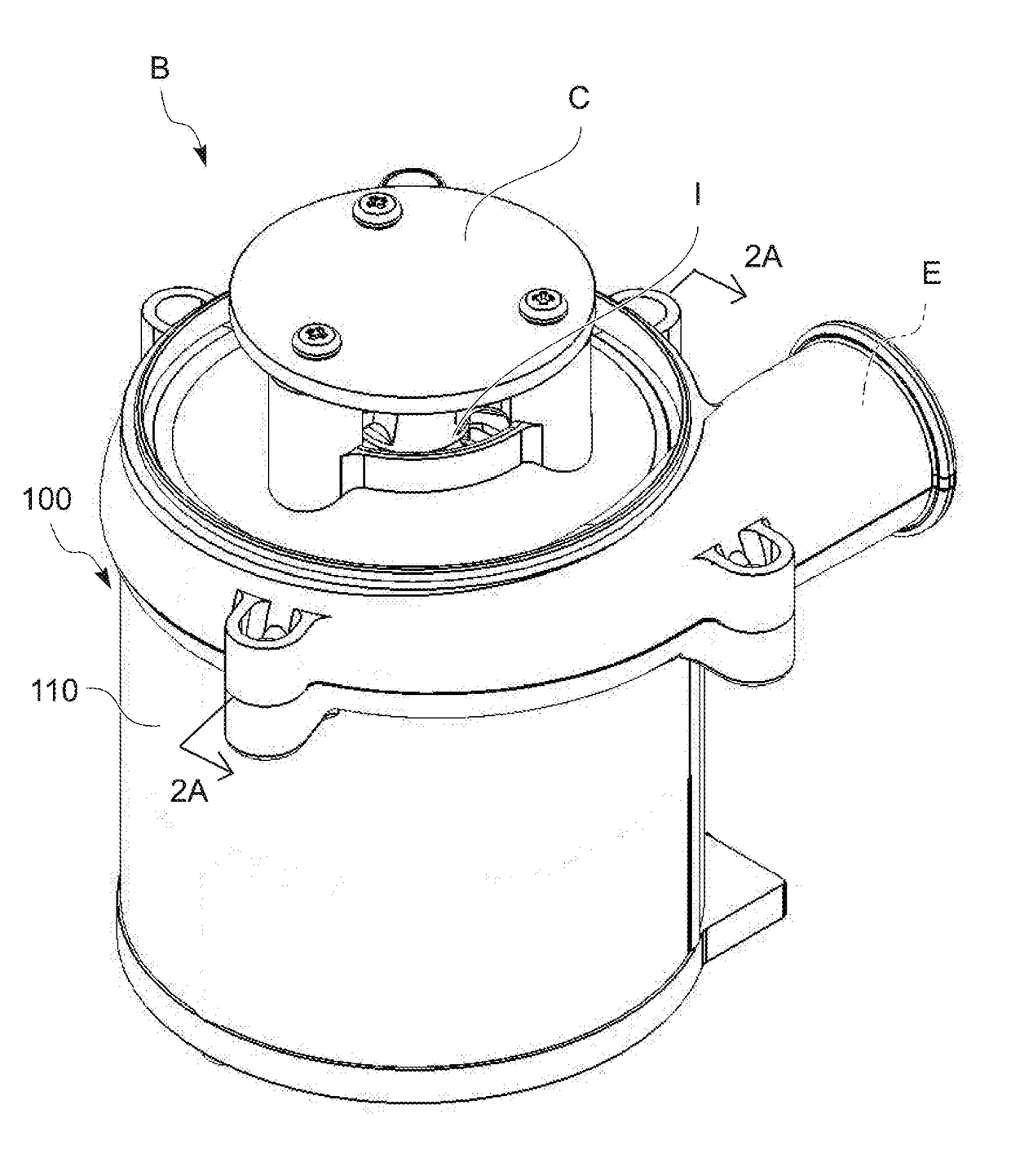
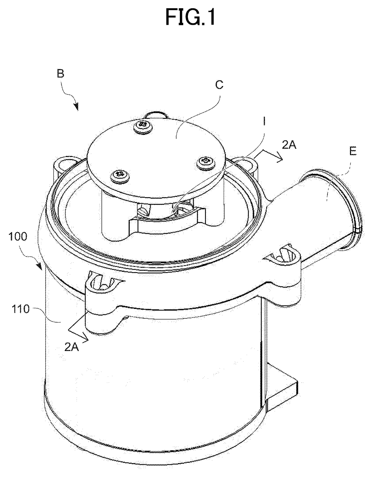
[0052]Hereinafter, a fan instrument B using a motor 100 which serves as the present invention will be described on the basis of FIGS. 1 to 6B, and a motor control system MS using the motor 100 will be described on the basis of FIGS. 7 to 11.

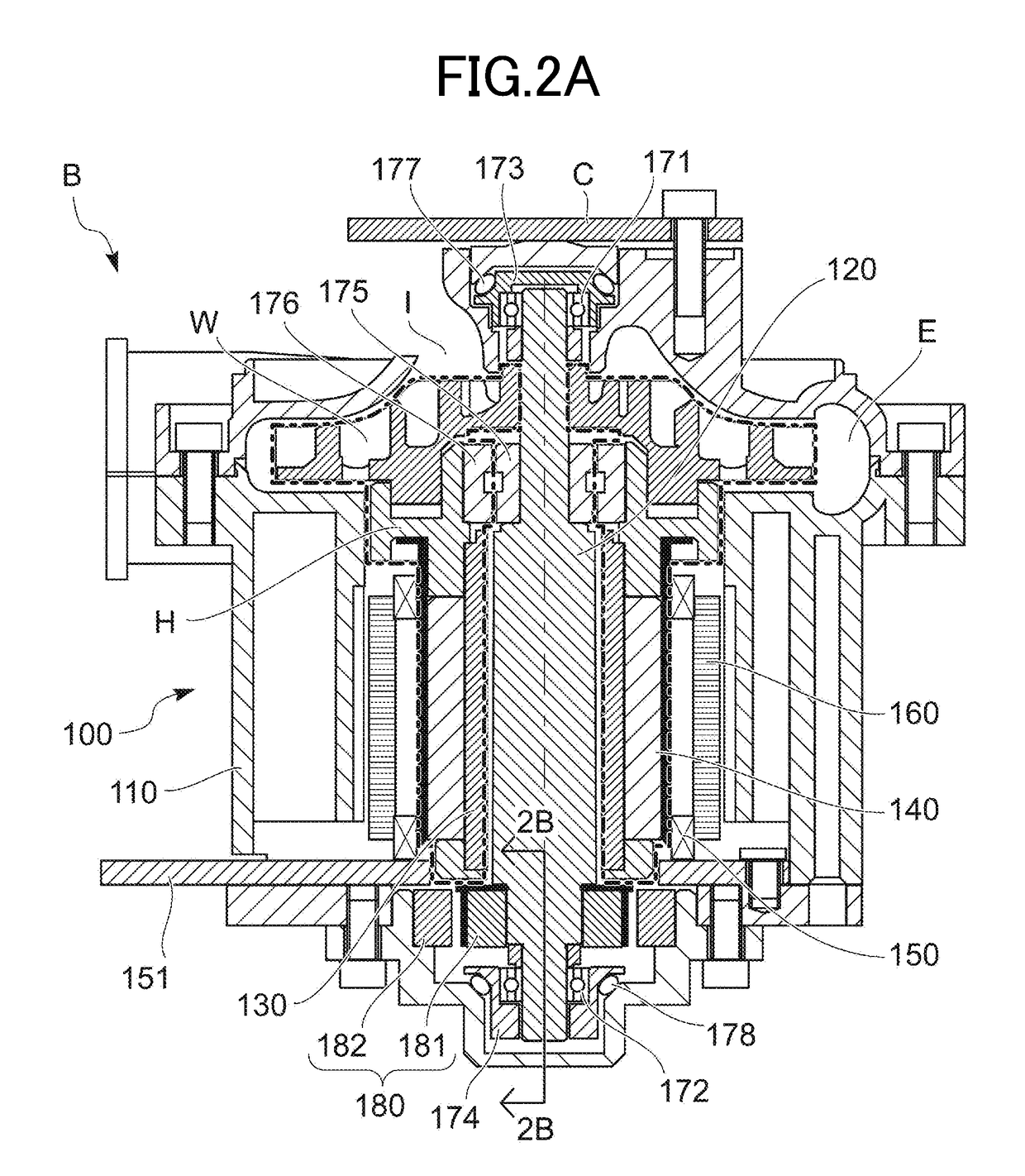
[0053]FIG. 1 is a perspective view of a fan instrument B using the motor 100 which serves as the first embodiment of the present invention. FIG. 2A is a sectional side view as seen in reference numerals 2A-2A of FIG. 1, which illustrates rotation in a state where a motor shaft 120 and a sleeve 130 are separated from each other. FIG. 2B is a sectional side view of major parts as seen in reference numerals 2B-2B of FIG. 2A. FIGS. 3A and 3B are sectional side views respectively corresponding to FIGS. 2A and 2B, and illustrating rotation of the time when the sum of a rotation-time viscous friction torque Ta of a dynamic pressure gas bearing and a contact friction torque Tka possibly making damage to the dynamic pressure gas bearing by swinging contac...

second embodiment

[0141]Next, a fan instrument B using a motor 200 which serves as the present invention will be described on the basis of FIGS. 12A and 12B.

[0142]FIG. 12A is a sectional side view of the fan instrument B using the motor 200 which serves as the second embodiment of the present invention. FIG. 12B is a sectional side view of major parts as seen in reference numerals 12B-12B of FIG. 12A.

[0143]The motor 200 of the second embodiment is a shaft rotation-type motor which is modified from the sleeve rotation-type motor 100 of the first embodiment. Many elements of the motor 200 are common to those of the motor 100 of the first embodiment. Thus, the common matters will not be described in detail and will be simply identified with similar numbers in 200s.

[0144]In the motor 200 of the fan instrument B serving as the second embodiment of the present invention, as illustrated in FIG. 12A, the impeller W and the hub H are attached to be rotated integrally with a motor shaft 220. A rotor case 241 i...


PUM


Abstract

This invention prevents seizure of a dynamic pressure gas bearing caused upon swinging contact between a motor shaft and a sleeve and an increase in contact friction torque. It also detects rotation of auxiliary bearings. A motor includes auxiliary bearings in series with a dynamic pressure gas bearing, and a non-contact detent torque generation mechanism parallel to the auxiliary bearings suppresses rotation of the auxiliary bearings. Where Ta denotes rotation-time viscous friction torque of the dynamic pressure gas bearing, Tka denotes contact friction torque possibly causing damage to the dynamic pressure gas bearing, Tb denotes rotation friction torque of the auxiliary bearings, and Tdmax denotes maximum torque generated when rotation of the auxiliary bearings is suppressed by the non-contact detent torque generation mechanism, (Ta+Tka)>(Tb+Tdmax)>(Ta), and the rotation detecting means detects the rotation of the auxiliary bearings.

Description

FIELD OF THE INVENTION[0001]The present invention relates to a motor including a dynamic pressure gas bearing, in which a rotating body is rotated at high speed, and in particular, relates to a motor used in a fan instrument called a sirocco fan, a turbo blower, or the like, and a motor control system including this motor.BACKGROUND OF THE INVENTION[0002]Conventionally, there is a known motor in which a dynamic pressure gas bearing supporting a shaft by a sleeve is used. Such a motor is disclosed in Japanese Unexamined Utility Model Application Publication No. 03-101154.[0003]However, the above conventional motor has a structure in which simply by rotating the shaft, a dynamic pressure is generated between an outer circumferential surface of the shaft and an inner circumferential surface of the sleeve, so that bearing rigidity is provided. Thus, when, due to an external disturbance or the like added to the motor, the shaft and the sleeve swing relatively in the direction in which th...

Claims


Application Information

Patent Timeline
IPC IPC(8): F04D29/05F16C41/02H02K7/08F04D29/056
CPCF04D29/05F04D29/056H02P29/00H02K7/08F16C41/02F04D25/08F04D27/001F04D29/051F04D29/057F04D29/059F04D29/281F16C19/54F16C32/0614H02K7/083H02K7/14H02K2213/06
Inventor KANAI, TAKASHIMATSUSHITA, HIROKI
Owner COPAL ELECTRON CO LTD
Why Eureka
Try Eureka