
Electromagnetic distributed direct drive for aircraft

Active Publication Date: 2017-09-28
CHRETIEN PASCAL
View PDF3 Cites 37 Cited by
  • Summary
  • Abstract
  • Description
  • Claims
  • Application Information

AI Technical Summary

Benefits of technology

The invention is about a new type of power train system for aircraft that uses an internal network of optical or electrical communication to improve reliability and performance. This system reduces the need for communication with external systems and allows for early fault warning and resilience to electromagnetic interference. It also enables regenerative breaking to prevent over speeding of the airscrew. Overall, this new system outlines the internal architecture of a fault-tolerant distributed direct drive power train that improves safety and performance compared to traditional gearboxes and electric topologies.

Problems solved by technology

The safety of the aircraft would no longer be adequately assured in the event of the failure of one of the electric motors.
The motors and controllers are physically separated and interconnected via power cabling, inducing vulnerability to EMP, EMI, ESD aggressions combined with added system weight.
This layout is presented at system level and does not disclose any fault tolerant topologies, or any form of solution addressing EMP, EMI, ESD hardening; that is, in the event of strong electromagnetic pulses, radio interference, lightening strike, or strong ESD discharge the controllers' integrity may be compromised and the craft's safety will be jeopardized.
The resultant weight budget of the distributed drive is subsequently compared with heavier redundant systems.
The disclosures do not teach the internal architecture of such drive down to component level, nor do they disclose a possible solution improving the resilience to EMP, EMI, ESD aggressions.
Since each one rarely fails, and the sub components are expected to fail independently, the probability of all three failing is calculated to be extremely small; often outweighed by other risk factors, e.g., human error.
DE 10 2010021024A1 details the architecture at system level and does not disclose the internal design of the motor system down to component level, nor does it provide a practical solution addressing the resilience to EMP, EMI, ESD aggressions (the cabling & connections between the external control unit and the motor system present an inherent vulnerability).
The absence of resident intelligence imbedded within the motor system and its inability to autonomously manage multiple faults causes the motor system to be completely reliant on the remote control unit for proper operation.
Furthermore, the absence of transverse communication between the various power-electronics components integrated into the motor requires that all decisions processes be externally executed by the remote control unit, also.
In case of failure of the control unit or loss of communication, the safety of the aircraft would be compromised.
Besides, the connections between the external control unit and the motor system present an obvious vulnerability.
The safety of the aircraft would be compromised, should the connection between the external control unit and the motor fail.
This system of propulsion necessitates a relatively large physical size, because the motor assembly is over-dimensioned for the envisaged redundancy.
No particular design addresses EMP, EMI, ESD resilience or fault tolerant architecture other than the redundant motor system.

Method used


Image

  • Electromagnetic distributed direct drive for aircraft
  • Electromagnetic distributed direct drive for aircraft
  • Electromagnetic distributed direct drive for aircraft

Examples


Embodiment Construction

[0098]The term “aircraft” as used herein, is intended to encompass various flying craft including fixed-wing aircraft, rotary-wing aircraft (including single and multiple rotors), flapping-wing aircraft and other airborne vehicles of various scales.

[0099]The term “airscrew” as used herein is intended to encompass various types of rotors and propellers that convert rotary motion from a motor to provide a propulsive force.

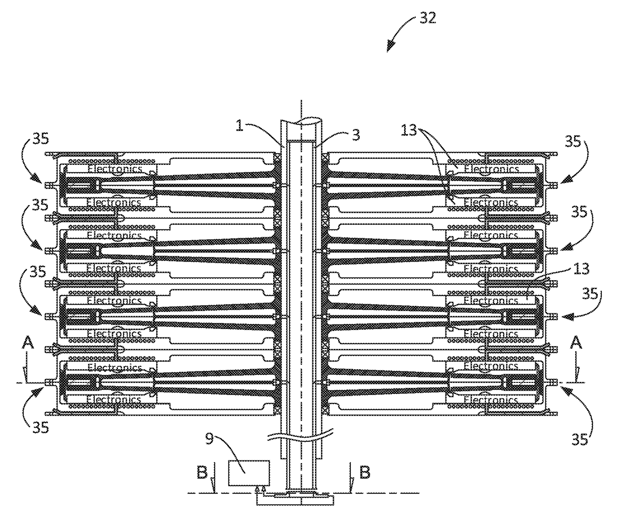
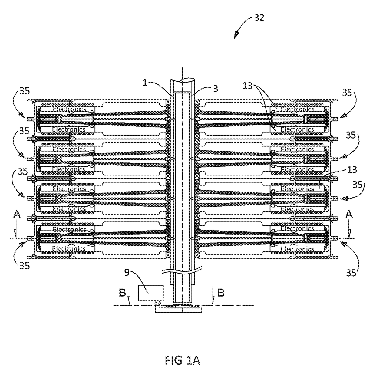
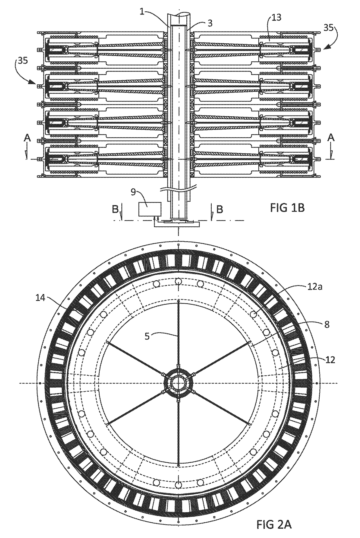
[0100]Referring to FIGS. 1A and 1B, the axial flux electromagnetic distributed direct drive [32] is composed of a stack of motor elements [35]. Conversely, FIGS. 14A and 14B depict an electromagnetic distributed direct drive [32] is composed of a stack of motor elements [35]. Each motor element [35] is connected to the shaft [1] to cause one or more airscrews [29] to rotate (see FIG. 20).

[0101]Referring now to FIGS. 2A and 2B, there are shown top views of cross sections through an axial flux electromagnetic distributed direct drives of FIGS. 1A and 1B respectively. C...


PUM


Abstract

A fault tolerant, optically or electrically managed, EMP resilient electromagnetic distributed direct drive powertrain applied to provide lift and / or propulsion and / or attitude control to an aircraft. The electromagnetic distributed direct drive being network based, capable of autonomous operations and decisions such as pilot input interpreting mode, load distribution, fault management, self-healing operations, electrical and mechanical health monitoring, as well as electrical and mechanical fault prediction.

Description

TECHNICAL FIELD OF THE INVENTION[0001]An optically or electrically interconnected electromagnetic distributed direct drive (also referred to as EMD3) provides an alternative to legacy mechanical drive train traditionally installed in conventional rotary-wing or fixed-wing aircrafts.BACKGROUND[0002]Conventional rotary-wing aircrafts use a set of complex mechanical gearboxes that convert the high rotation speed of gas turbines into the low speed / high torque required to drive the rotor(s). Unlike powerplant, mechanical gearboxes cannot be duplicated for redundancy, hence remain a known single point of failure (SPOF) consistently affecting helicopter reliability and safety. In-flight catastrophic gear failure usually results in gearbox jamming and subsequent fatalities, whereas loss of lubrication can trigger onboard fire. This fact is eloquently documented by regular crash reports issued by government bodies in charge of civil and military aviation (e.g. EASA, BASI and NTSB). Furthermo...

Claims


Application Information

Patent Timeline
IPC IPC(8): B64C27/14H02K21/24H02K11/33H02K21/14B64D35/02B64D27/24
CPCB64C27/14B64D35/02B64D27/24H02K11/33H02K2213/12H02K21/24H02K16/00H02K2213/06H02K21/14Y02T50/40Y02T50/60
Inventor CHRETIEN, PASCAL
Owner CHRETIEN PASCAL
Learn More