
Ionospheric scintillation prediction

Active Publication Date: 2017-09-28
FUGRO INTERSITE
View PDF1 Cites 19 Cited by
  • Summary
  • Abstract
  • Description
  • Claims
  • Application Information

AI Technical Summary

Benefits of technology

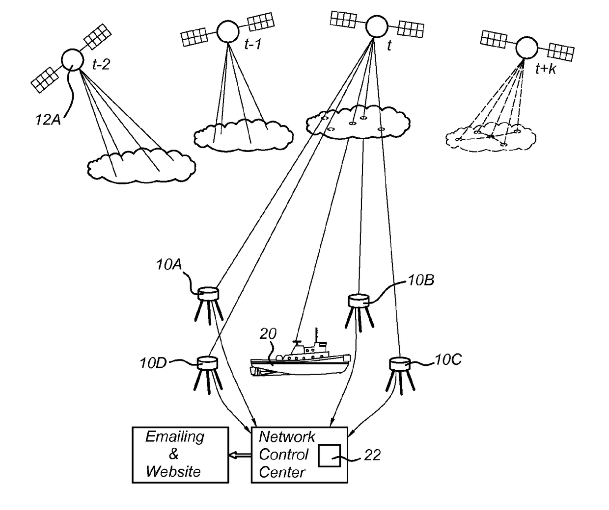
The patent describes a method for predicting the phase scintillation of signals received from satellites to improve accuracy in positioning. The method separates the spatial and temporal prediction, allowing for a more accurate prediction of the expected phase scintillation at the user location. The method also takes into account the dilution of precision for the combination of satellites available and the likely error for a given satellite. The method uses a multiplicative Holt-Winters prediction model and determines ionosphere pierce points for signals received from the given satellite for each reference station. The method further includes determining the height of the ionospheric thin layer with which the scintillation is primarily associated. The method allows existing networks of reference stations to be used without requiring additional scintillation receivers.

Problems solved by technology

Thus if a high degree of scintillation is predicted for a given satellite, this may not lead to a lack of precision if a number of other (undisturbed) satellites will be visible at that moment in time.

Method used


Image

  • Ionospheric scintillation prediction
  • Ionospheric scintillation prediction
  • Ionospheric scintillation prediction

Examples


Embodiment Construction

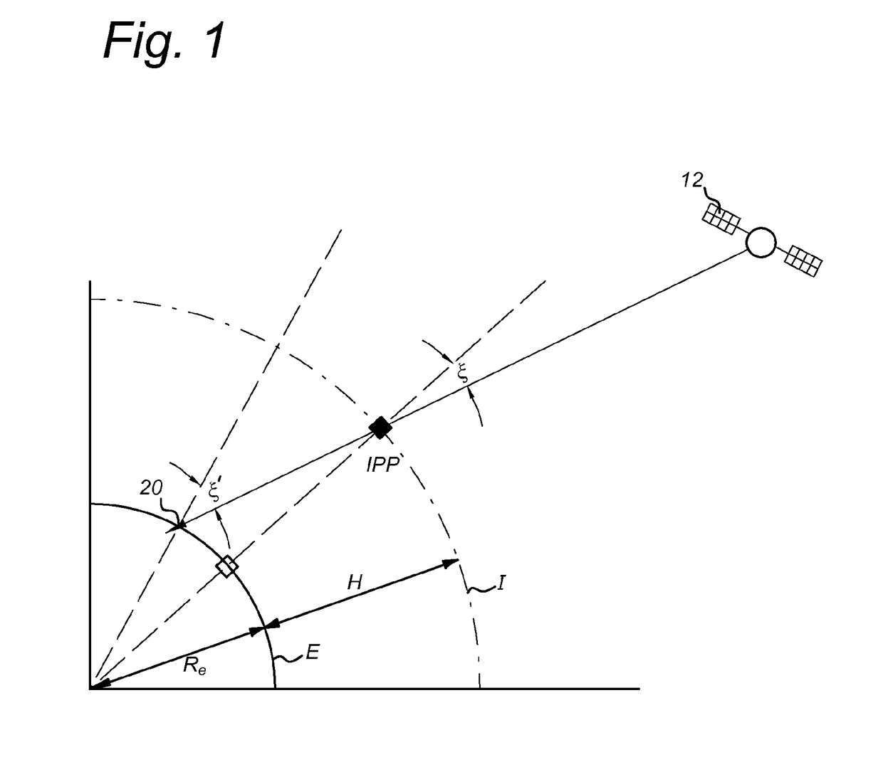
[0042]In order to better understand the context of the invention, a brief introduction to the calculation of ionospheric effects is provided, on which the invention is based. Due to the Earth's rotation, the ionosphere is a highly dynamic medium and the electron density can vary significantly from minute to minute at a given location resulting in temporal and spatial variations of TEC. FIG. 1 shows the geometry of the thin-layer ionosphere I at height H above the Earth E, including a satellite 12 visible from a user location 20. The line of sight between the satellite 12 and user location 20 passes the ionosphere I at the ionospheric pierce point (IPP). The satellite zenith angle ξ at the IPP is thus distinct from the satellite zenith angle ξ′ measured at the user location 20. For simplicity and to exclude height dependency of TEC, a thin-layer approximation is used for the ionosphere and the slant TEC is mapped onto the vertical TEC using a simple cosine function:

VTEC(t,φ,λ,H)=m(ξ)...


PUM


Abstract

A method of generating scintillation prediction data comprises: •a) for a plurality of satellites (12A), and reference stations (10A, 10B, 10C, 10D) measuring phase scintillation data, satellite by satellite for each reference station during multiple epochs (t−2, t−1, t, t+k); •b) forecasting an expected phase scintillation value for each satellite and reference station for a period of at least 24 hours based on a cyclical prediction model; •c) for a given user location (20) and a given satellite, spatially interpolating the expected phase scintillation values of the plurality of reference stations to determine a predicted phase scintillation index; •d) repeating step c) for further satellites visible from the user location.

Description

BACKGROUND OF THE INVENTION[0001]1. Field of the Invention[0002]The present invention relates to methods of predicting ionospheric scintillation and in particular methods of providing a user of a Global Navigation Satellite System (GNSS) with information relating to the reliability of positioning data derived from individual satellites.[0003]2. Description of the Related Art[0004]The ionosphere is a region of the Earth's atmosphere, from about 80 to 1000 km above its surface, where significant numbers of free electrons and ions are present. The free electrons and ions are produced by solar ionizing radiation (extreme ultraviolet and X-ray radiations) and by collisions of energetic particles (solar wind) with the neutral particles at the upper atmosphere. Positive ions and electrons in the upper atmosphere are usually well mixed and form electrically neutral plasma.[0005]The ionosphere can affect L-band, and therefore GNSS, signal propagation and can therefore be important for the ac...

Claims


Application Information

Patent Timeline
IPC IPC(8): G01S19/07G01S19/13G01S19/10G01S19/08G01S19/09
CPCG01S19/07G01S19/08G01S19/13G01S19/10G01S19/09G01S19/258
Inventor MEMARZADEH, YAHYA
Owner FUGRO INTERSITE
Learn More