
Electronic cigarette temperature control system and method, and electronic cigarette with the same

a temperature control system and electronic cigarette technology, applied in the field of tobacco substitutes, to achieve the effect of avoiding the production and release of harmful substances, good taste, and saving energy

Active Publication Date: 2017-10-05
JOYETECH EURO HLDG
View PDF9 Cites 49 Cited by
  • Summary
  • Abstract
  • Description
  • Claims
  • Application Information

AI Technical Summary

Benefits of technology

The patent describes an electronic cigarette with a system for controlling the temperature of the heating element. The system uses pre-stored formulas to calculate the temperature of the heating element based on voltage drop, resistance value, and temperature of the detection element. The system also monitors the temperature of the thermostatic switch and adjusts the connection between the power supply and the heating element accordingly to maintain the temperature within a safe range. This helps to avoid the production and release of harmful substances, ensures good taste, saves energy, prevents overheating of the housing, and prevents thermal ageing of the inner components of the electronic cigarette. Additionally, the patent also mentions an input device that allows the user to set the operating temperature of the heating element based on their need.

Problems solved by technology

An excessive temperature of the heating member may lead the smoke liquid, the wax, or the tobacco to produce and release some substances which are harmful to health.

Method used


Image

  • Electronic cigarette temperature control system and method, and electronic cigarette with the same
  • Electronic cigarette temperature control system and method, and electronic cigarette with the same
  • Electronic cigarette temperature control system and method, and electronic cigarette with the same

Examples


first embodiment

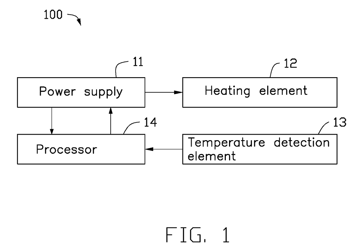
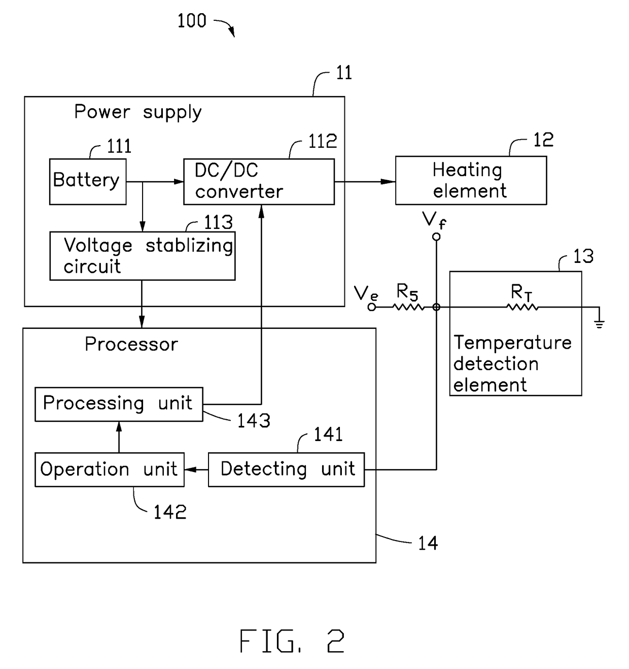
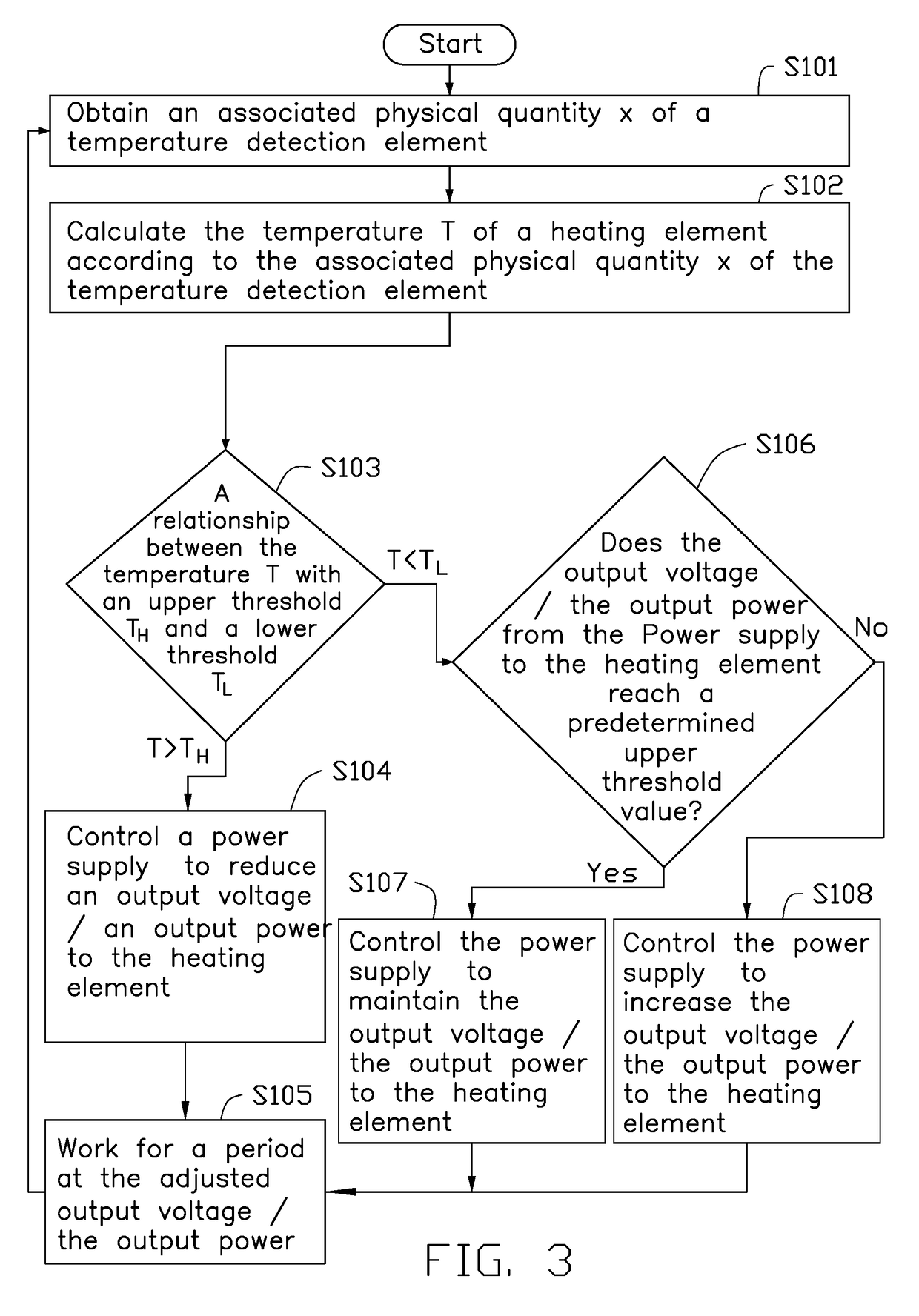
[0127]FIG. 1 illustrates an electronic cigarette temperature control system 100. The electronic cigarette temperature control system 100 can include a power supply 11, a heating element 12, at least one temperature detection element 13, and a processor 14. The power supply 11 can be electrically coupled to the heating element 12 and the processor 14. The at least one temperature detection element 13 can be electrically coupled to the processor 14. The heating element 12 can heat smoke liquid, wax, or tobacco to generate vapor, causing a user to experience a simulation of tobacco smoking after the power supply 11 supplies power to the heating element 12.

[0128]The at least one temperature detection element 13 can detect a change of a temperature T of the heating element 12. The temperature t of the at least one temperature detection element 13 can increase when the temperature T of the heating element 12 increases. An associated physical quantity x of the temperature detection element...

third embodiment

[0160]FIG. 6 illustrates the electronic cigarette temperature control system 300. The electronic cigarette temperature control system 300 can include a power supply 31, a thermostatic switch 36, and a heating element 32 coupled in sequence. The heating element 32 can heat smoke liquid, wax, or tobacco, causing a user to experience a simulation of tobacco smoking after the power supply 31 supplies power to the heating element 32.

[0161]The thermostatic switch 36 can turn on a connection between the power supply 31 and the heating element 32 or turn off the connection between the power supply 31 and the heating element 32 in the role of temperature. The temperature ts of the thermostatic switch 36 can increase when the temperature T of the heating element 32 increases. When the temperature ts of the thermostatic switch 36 is less than a switch temperature TM of the thermostatic switch 36, the thermostatic switch 36 can turn on the connection between the power supply 31 and the heating ...

fourth embodiment

[0165]In the fourth embodiment, the electronic cigarette temperature control system 400 can include a processor 44. The thermostatic switch 36 can be electrically coupled to the processor 44. The thermostatic switch 36 cannot control the connection between the power supply 31 and the heating element 32 directly. The processor 44 can control the output voltage / the output power from the power supply 31 to the heating element 32 after the processor 44 judges according to an on or off state of the thermostatic switch 36.

[0166]The temperature ts of the thermostatic switch 36 can increase when the temperature T of the heating element 32 increases. When the temperature ts of the thermostatic switch 36 is less than a switch temperature TM of the thermostatic switch 36, the thermostatic switch 36 can perform action A. When the temperature ts of the thermostatic switch 36 is greater than a switch temperature TM of the thermostatic switch 36, the thermostatic switch 36 can perform action B. Th...


PUM


Abstract

An electronic cigarette temperature control system includes a power supply, a heating element, a temperature detection element, and a processor. The power supply is electrically coupled to the heating element and the processor. The temperature detection element is configured to detect a change of a temperature T of the heating element and output the change of the temperature T of the heating element to the processor. The processor is electrically coupled to the temperature detection element. The processor is configured to determine the temperature t of the temperature detection element according to an associated physical quantity x of the temperature detection element, and calculate the temperature T of the heating element according to the temperature t of the temperature detection element. A related electronic cigarette temperature control method and a related electronic cigarette are also provided.

Description

CROSS-REFERENCE TO RELATED APPLICATIONS[0001]This application is a Continuation-In-Part of PCT Application No. PCT / CN2015 / 087597 filed on Aug. 20, 2015, entitled “TEMPERATURE CONTROL SYSTEM AND CONTROL METHOD THEREOF, AND ELECTRONIC CIGARETTE CONTAINING SAID TEMPERATURE CONTROL SYSTEM”.[0002]This application is a Continuation-In-Part of PCT Application No. PCT / CN2015 / 087599 filed on Aug. 20, 2015, entitled “TEMPERATURE CONTROL SYSTEM AND CONTROL METHOD THEREFOR, AND ELECTRONIC CIGARETTE CONTAINING TEMPERATURE CONTROL SYSTEM”.[0003]This application is a Continuation-In-Part of PCT Application No. PCT / CN2015 / 087600 filed on Aug. 20, 2015, entitled “TEMPERATURE CONTROL SYSTEM AND CONTROL METHOD THEREOF, AND ELECTRONIC CIGARETTE CONTAINING SAID TEMPERATURE CONTROL SYSTEM”.[0004]This application claims priority to Chinese Patent Application No. CN201510033982.9 filed on Jan. 22, 2015 in the China Intellectual Property Office, the contents of which are incorporated by reference herein.FIE...

Claims


Application Information

Patent Timeline
IPC IPC(8): A24F47/00G05D23/24G05D23/19A24F40/10A24F40/57
CPCA24F47/008G05D23/1919G05D23/24G05D23/1917G05D23/2401A24F40/10A24F40/57G05B6/02A24C5/01
Inventor QIU, WEI-HUA
Owner JOYETECH EURO HLDG
Learn More