System and method for testing the validity of bim-designed electrical wiring pathways

Active Publication Date: 2017-10-05
M C DEAN INC
View PDF0 Cites 62 Cited by
  • Summary
  • Abstract
  • Description
  • Claims
  • Application Information

AI Technical Summary

Benefits of technology

The testing system described in this patent is designed to check and confirm the validity of electrical and signal distribution systems designed using a BIM tool. The system extracts information from the BIM tool and calculates the shortest distances between devices and their assigned distribution sources, confirming if the pathways are valid or invalid. This allows for real-time feedback and ensures that no invalid pathways are included in the final design. Additionally, the system ensures that the circuiting between devices and their sources is valid, ensuring the overall validity of the design.

Problems solved by technology

Unfortunately, as useful as BIM tools are, their use rarely results in a completely error-free design.
For example, many building owners limit the length of MC cable that may be used in an electrical or signal wiring pathway, and the BIM-designed pathway may require a length of MC cable in excess of such limitation.
Finally, the applicant has observed instances where the pathway is impractical or excessively expensive to build in the field.
Such errors can arise from a number of causes, including modeler errors in assigning a proper string of pathway elements between the devices and their assigned circuits, or modeler oversights after changes are made, such as when new devices are added or the location of one or more devices is changed.
The ever-increasing number and density of wiring pathways in modern buildings such as hospitals and data centers increases the probability of such errors occurring in the future, as it becomes ever more difficult for the modeler to perceive such errors in the detail-laden floor plans.
These design errors often necessitate the installation of additional pathway elements, or the replacement of such elements.
Worse yet, such design errors are typically not discovered until after the construction of walls, ceilings, and other structures which obstruct the installation of the additional conduits, junction boxes and / or metal-clad (MC) cables required to correct the error.
The time and expense associated with the installation of the additional conduits, junction boxes and metal-clad (MC) cables necessary to correct the errors is often substantial, sometimes costing hundreds of thousands of dollars.

Method used


Image

  • System and method for testing the validity of bim-designed electrical wiring pathways
  • System and method for testing the validity of bim-designed electrical wiring pathways
  • System and method for testing the validity of bim-designed electrical wiring pathways

Examples


Embodiment Construction

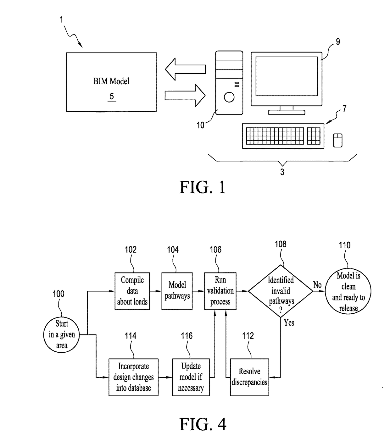
[0027]With reference to FIG. 1, the testing system 1 generally comprises a digital processor 3 that is electrically or optically connected to or otherwise in communication with a BIM modeling tool 5. The processor 3 includes a user interface 7 in the form of a keyboard and mouse combination, a display screen 9, and a processing unit 10 which may be any one of a number of commercially-available computer processors. In the preferred embodiment, the BIM modeling tool is Autodesk® Revit, although any one of a number of commercially available BIM modeling tools may form part of the system 1 of the invention.

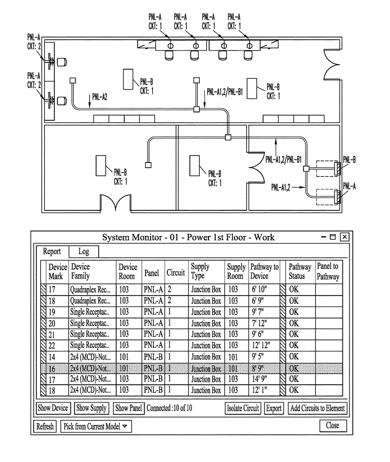
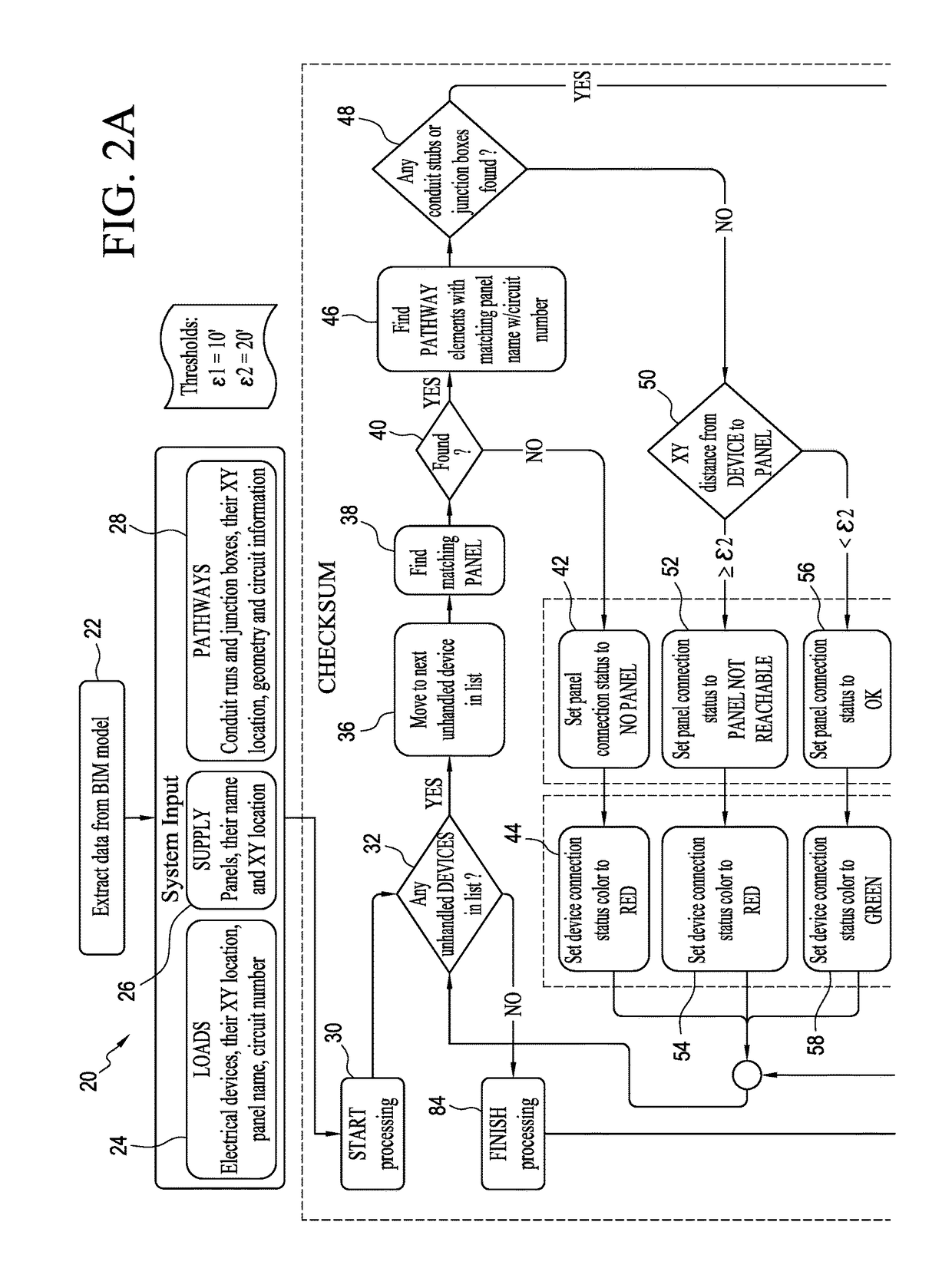
[0028]In contrast to prior art BIM tools, the system 1 automatically and simultaneously displays a real-time report on the display screen 9 clearly indicating the validity or invalidity of the resulting pathway as soon as a system user assigns a circuit to a pathway. The manner in which the system 1 accomplishes this task is summarized in FIGS. 2A and 2B which comprise a flowchart 20 ...


PUM


Abstract

A testing system and method are provided for verifying that a BIM-designed electrical distribution system in a building provides a valid, cost-effective electrical wiring pathway between every device and its assigned electrical distribution source. The system includes a digital processor having access to the informational content of the BIM-designed electrical distribution system, and a user interface and display screen connected to the digital processor. In operation, the digital processor extracts from the BIM-designed electrical distribution system the x-y locations of the devices, distribution sources such as electrical supply panels, and wiring pathway elements (e.g. conduits, junction boxes, etc.) forming electrical pathways. As the user lays out the pathways, the processor immediately informs the user, via the display screen, whether the distances between the device and the nearest exit point of the associated pathway and the distribution source and the nearest entry point of the associated pathway are within pre-selected, empirically-determined tolerances.

Description

FIELD[0001]This invention generally relates to electrical distribution systems designed by building information modeling (BIM) tools, and is specifically concerned with a system and method for testing the validity of electrical wiring pathways in such distribution systems.BACKGROUND[0002]Building information modeling (BIM) tools are frequently used by building designers to design the layout of the electrical and signal distribution systems of the building. Such systems include the power distribution system of the building, which in turn is comprised of devices (e.g. power outlets, light fixtures, ventilation fan motors, etc.), power supply panels, circuits between the devices and the panels, and the electrical pathway elements that carry the circuits (e.g. conduits, junction boxes, metal-clad (MC) cables, etc.). Such systems also include control and signal distribution systems, which again are comprised of devices (e.g. fire alarm sensors, security cameras, control actuators, etc.),...

Claims


Application Information

Patent Timeline
IPC IPC(8): G06F17/50
CPCG06F17/5004G06F30/13G06F2111/04G06F2113/16
Inventor DEAN, WILLIAM H.KARSHAKEVICH, ALEXEYTOMKEIEV, OLEKSANDR
Owner M C DEAN INC
Why Eureka
Try Eureka