Polishing apparatus and wafer polishing method

a polishing apparatus and index system technology, applied in lapping machines, manufacturing tools, abrasive surface conditioning devices, etc., can solve the problems of difficult to adversely affect the quality of the wafer, and reduce the thickness of the dressing mechanism, so as to improve the stiffness shorten the length of the polishing shaft, and prolong the stroke width

Active Publication Date: 2017-10-26
SHIN-ETSU HANDOTAI CO LTD +1
View PDF5 Cites 6 Cited by
  • Summary
  • Abstract
  • Description
  • Claims
  • Application Information

AI Technical Summary

Benefits of technology

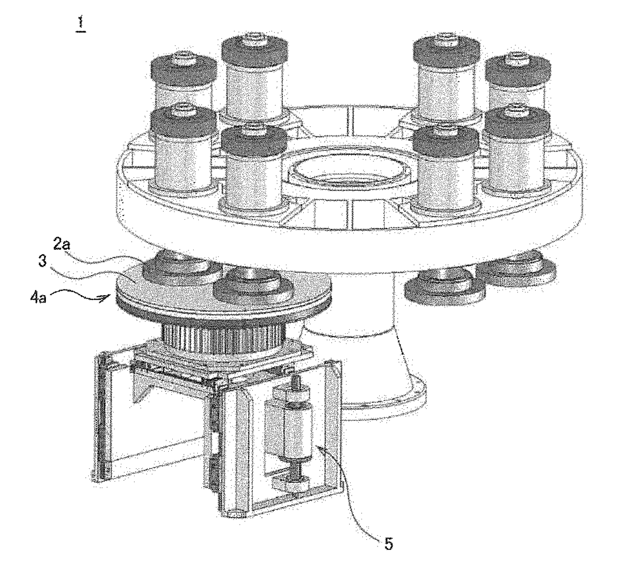
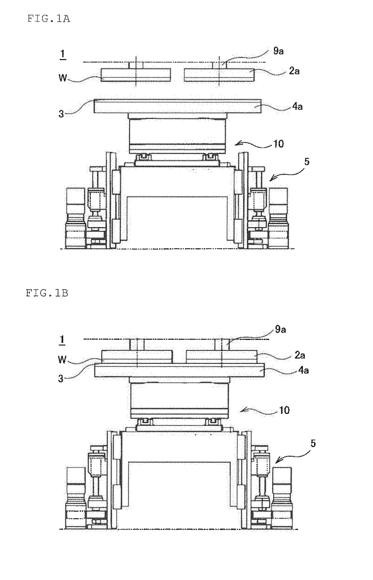
[0047]According to the polishing apparatus, and the polishing method using the polishing apparatus of the present invention, because the turn table upward and downward movement mechanism can move the turn table upward and downward, it is not necessary to move the polishing head upward and downward with a long stroke width, so that it is possible to shorten the length of the polishing shaft. Therefore, because stiffness of the polishing shaft is improved, it is possible to red

Problems solved by technology

While it is possible to suppress clogging of the polishing pad through brushing and dressing, because the wafer cannot be polished during brushing and dressing, productivity degrades.
Therefore, it is difficult to reduce the thickness of the dressing mechanism, and, for example, in the case of a typical polishing apparatus for wafer having a diameter of 300 mm, a stroke width of 120 mm or greater is required for upward and downward movement of the polishing head to avoid collision with the dressing mechanism, and a length of the polishing shaft is required to be longer than this stroke width.
In the case where such displacement occurs at the polishing shaft, there is a problem that fluctuation becomes large at an edge portion of the wafer to be polished, which adversely affects quality of the wafer.
However, in the case where stiffness of a rotating portion is increased to suppress a displacement amount of the polishing shaft, weight of an upper part of the polishing apparatus becomes heavy.
If the weight of the upper part of the polishing apparatus becomes heavy, because, as a result, a total weight of the apparatus considerably increases, which causes constraints to an area where the apparatus is provided, it is difficult to improve accuracy.
Further, when the polishing head performs rotation operation, in order to avoid physical interference between the polishing head and the dressing mechanism, th

Method used


Image

  • Polishing apparatus and wafer polishing method
  • Polishing apparatus and wafer polishing method
  • Polishing apparatus and wafer polishing method

Examples


example 1

[0107]The polishing apparatus of the present invention was prepared and shaft stiffness was evaluated. The prepared polishing apparatus supports polishing of a wafer having a diameter of 300 mm. The polishing head has a polishing head upward and downward movement mechanism for moving the polishing head upward and downward with a stroke width of 20 mm, and the turn table upward and downward movement mechanism has a stroke width of upward and downward movement of 100 mm.

[0108]First, influence in the case where moment load is applied on the polishing head and the polishing shaft while the wafer is polished was analyzed through simulation. Note that the simulation was performed using Solidworks simulation.

[0109]Concerning influence of the moment load, as illustrated in FIG. 7, an amount of displacement of the polishing head 2 in a parallel direction in the case where load F is applied on the polishing head 2 was obtained.

[0110]As conditions of the simulation, it was assumed that load in...

example 2

[0120]In the polishing apparatus of the present invention having the turn table upward and downward movement mechanism and the polishing head upward and downward movement mechanism, time required for the polishing head to move from the lowermost position to the uppermost position of the upward and downward movement was measured. Note that the stroke width of the polishing head upward and downward movement mechanism was set at 20 mm, and the upward and downward movement speed of the polishing head was set at 35 mm / second.

[0121]As a result, moving time was 1.1 seconds on average including time required for acceleration and deceleration.

example 3

[0125]The polishing pad was dressed using the polishing apparatus having the turn table upward and downward movement mechanism and the dressing mechanism of the present invention, and change of the thickness of the polishing pad through dressing was evaluated. As the polishing pad, a hard urethane foam polishing pad for which the thickness can be easily measured was used. Further, to allow the thickness of the polishing pad to easily change, a diamond dresser having a high removal effect of a polishing pad surface layer was used, a dressing period was extended, and dressing was repeatedly performed.

[0126]Then, before each dressing was started, the height of the turn table was adjusted according to abrasion of the polishing pad. Specifically, an amount of displacement of the polishing pad due to dressing was obtained from the thickness of the polishing pad before and after the dressing, and dressing was repeatedly performed while increasing the height of the turn table by an amount c...


PUM


Abstract

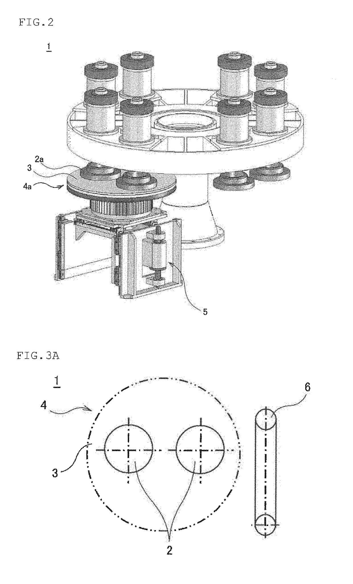
A polishing apparatus which is an index system polishing apparatus which includes a polishing head for holding a wafer, a plurality of turn tables to which polishing pads for polishing the wafer are attached, and a loading/unloading stage for loading the wafer to the polishing head or unloading the wafer from the polishing head, and which polishes the wafer while switching the turn tables to be used for polishing the wafer held at the polishing head by causing the polishing head to perform rotation movement, the polishing apparatus including a turn table upward and downward movement mechanism which allows the turn table to move upward and downward. With this polishing apparatus, it is possible to reduce an amount of displacement caused when moment load is applied on the polishing head during polishing.

Description

TECHNICAL FIELD[0001]The present invention relates to an index system polishing apparatus and a wafer polishing method.BACKGROUND ART[0002]A semiconductor wafer (hereinafter, also simply referred to as a wafer) typified by a silicon wafer is polished using a method for polishing the both sides at the same time or a method for polishing one side.[0003]In order to polish one side of the wafer, as illustrated in FIG. 11, a polishing apparatus 101 configured with a turn table 104 to which a polishing pad 103 is attached, a polishing agent supplying mechanism 108 for supplying a polishing agent 107 on the turn table 104, and a polishing head 102 for holding a wafer W to be polished, is widely used.[0004]The polishing apparatus 101 holds the wafer W with the polishing head 102 and performs polishing by supplying the polishing agent 107 on the polishing pad 103 from the polishing agent supplying mechanism 108, while respectively rotating the turn table 104 and the polishing head 102 to bri...

Claims


Application Information

Patent Timeline
IPC IPC(8): B24B37/34B24B37/04B24B53/017H01L21/304
CPCB24B37/345H01L21/304B24B53/017B24B37/04B24B27/0023B24B37/107B24B53/02H01L21/30625B24B25/00B24B27/0076B24B37/042
Inventor SATO, MICHITOUENO, JUNICHIISHII, KAORUKISHIDA, HIROMINAKANISHI, YUYAYODA, RYOSUKEKANAI, YOSUKE
Owner SHIN-ETSU HANDOTAI CO LTD
Why Eureka
Try Eureka