Integrated charger for vehicles and method of making same

Active Publication Date: 2017-10-26
GENERAL ELECTRIC CO
View PDF8 Cites 6 Cited by
  • Summary
  • Abstract
  • Description
  • Claims
  • Application Information

AI Technical Summary

Benefits of technology

[0012]The above embodiments enable rapid charging of the vehicle without the addition of any significant on board charger components. Further, the windings of the electromechanical device may remain connected to

Problems solved by technology

These additional dedicated components add extra cost and weight to the vehicle.
However, these converters have a limited output voltage restricting the ability to control charging the battery.
Furthermore, with 120 volt or 240 volt AC input, the DC output voltage cannot be higher than 170 volt or 340 volt when buck AC/DC converters are used.
A DC/DC converter can be included to match the full battery voltage range; however, this leads to increasingly large chargers to compensate fo

Method used


Image

  • Integrated charger for vehicles and method of making same
  • Integrated charger for vehicles and method of making same
  • Integrated charger for vehicles and method of making same

Examples


Example

[0018]For the purposes of promoting an understanding of the principles of the invention, reference will now be made to the exemplary embodiments illustrated in the drawings, and specific language will be used to describe the same. It will nevertheless be understood that no limitation of the scope of the invention is thereby intended. Any alterations and further modifications of the inventive features illustrated herein, and any additional applications of the principles of the invention as illustrated herein, which would occur to one skilled in the relevant art and having possession of this disclosure, are to be considered within the scope of the invention.

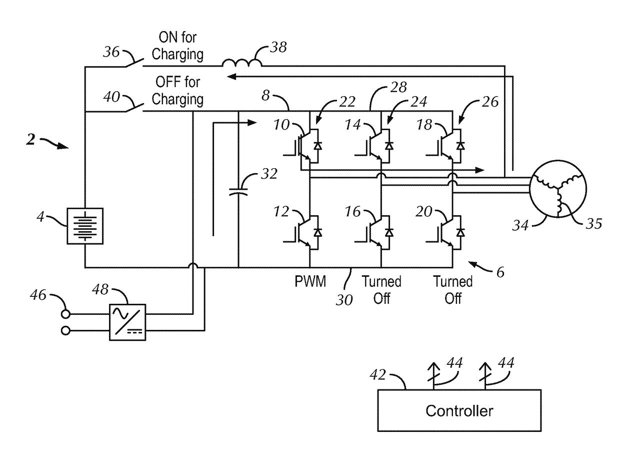
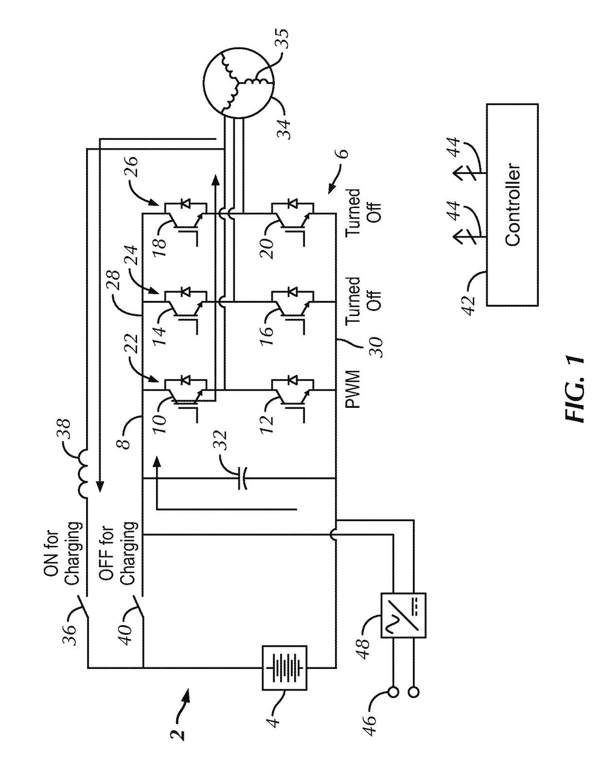
[0019]FIG. 1 illustrates a schematic diagram of a traction system 2 according to an embodiment of the present invention. Traction system 2 includes an energy storage device 4. In one embodiment, energy storage device 4 may be a battery, a flywheel system, a fuel cell, an ultracapacitor, or a combination of ultracapacitors and batte...


PUM


Abstract

According to some embodiments, a traction system is disclosed. The traction system includes a DC bus, an energy storage device coupled to the DC bus, and a voltage converter assembly coupled to the energy storage device. The voltage converter assembly includes a plurality of phase legs. The traction system further includes an electromechanical device including a plurality of windings coupled to the voltage converter assembly. The traction system also includes a switch coupled to the DC bus between the voltage converter assembly and the energy storage device. The traction system includes a controller configured to control the switch and the voltage converter assembly such that a phase leg and a winding of the electromechanical device form a DC/DC converter.

Description

BACKGROUND OF THE INVENTION[0001]Embodiments of the present invention relate generally to electric drive systems including hybrid and electric vehicles and to stationary drives that are subject to transient or pulsed loads and, more particularly, to transferring energy between an electrical storage device of the vehicle or drive and a power source external to the vehicle.[0002]Hybrid electric vehicles may combine an internal combustion engine and an electric motor powered by an energy storage device, such as a traction battery, to propel the vehicle. Such a combination may increase overall fuel efficiency by enabling the combustion engine and the electric motor to each operate in respective ranges of increased efficiency. Electric motors, for example, may be efficient at accelerating from a standing start, while combustion engines may be efficient during sustained periods of constant engine operation, such as in highway driving. Having an electric motor to boost initial acceleration...

Claims


Application Information

Patent Timeline
IPC IPC(8): B60L11/18B60K6/26H02P27/08
CPCB60L11/1811B60L11/1803H02P27/08B60K6/26B60Y2300/91B60Y2200/92B60Y2400/604B60Y2400/61Y10S903/906B60L53/24B60L2210/10Y02T10/7072Y02T90/14B60L53/22B60L50/51B60L53/20B60L50/60Y02T10/70B60L2210/12Y02T10/72B60L2220/56B60L2210/40B60L2240/527B60Y2200/90Y02T90/12
Inventor HUH, KUM KANGPAN, DI
Owner GENERAL ELECTRIC CO
Why Eureka
Try Eureka