Output controller for an engine controller, engine controller, and engine system

a technology of output controller and engine, which is applied in the direction of engine-driven generator propulsion, mechanical equipment, transportation and packaging, etc., can solve the problems of inability to achieve optimal power regulation and limited range of such electric vehicles, and achieve improved power regulation, reduced consumption, and increased fuel consumption

Inactive Publication Date: 2017-11-09
ROBERT BOSCH GMBH
View PDF1 Cites 5 Cited by
  • Summary
  • Abstract
  • Description
  • Claims
  • Application Information

AI Technical Summary

Benefits of technology

[0018]The knowledge on which the present invention is based is that regulation at optimum efficiency is not possible using conventional control and regulating systems for electric vehicles with a range extender and an increased fuel consumption is produced thereby.
[0019]The idea on which the present invention is based now involves taking this knowledge into account and providing a possibility in which a closed control loop is used with respect to the power of the engine system, thus making it possible to carry out improved power regulation with reduced consumption.
[0020]For this purpose, the present invention provides for the required desired mechanical power to be adapted on the basis of an efficiency of the overall system. Furthermore, the present invention also provides for a mass moment of inertia of the internal combustion engine to be used when setting the torque required by the internal combustion engine.
[0021]The engine control system according to the invention finally provides for the generator to be controlled on the basis of the desired speed for the generator and on the basis of the output torque of the internal combustion engine.
[0022]As a result of the described structure, the present invention makes it possible to control the engine system with a minimum possible fuel consumption. In this case, a desired electric power can be produced at the same time. Furthermore, the power controller can quickly follow a desired change in the desired power. This is important, for example, because power which is produced by recuperation during braking must be immediately compensated for by means of a corresponding power reduction if limitation to a maximum charging power of the battery system becomes effective at the same time.
[0023]Advantageous embodiments and developments emerge from the subclaims and from the description with reference to the figures.

Problems solved by technology

On account of the limited capacity of currently available electric energy stores, the range of such electric vehicles is limited.
Since the speed has to be regulated by changing the burner torque, power regulation at optimum efficiency is not possible with this structure.

Method used


Image

  • Output controller for an engine controller, engine controller, and engine system
  • Output controller for an engine controller, engine controller, and engine system
  • Output controller for an engine controller, engine controller, and engine system

Examples


Embodiment Construction

[0048]In all of the figures, identical or functionally identical elements and apparatuses have been provided with the same reference symbols unless indicated otherwise.

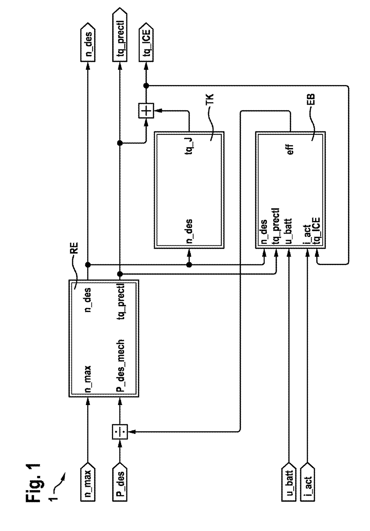
[0049]FIG. 1 shows a block diagram of one embodiment of a power controller 1 according to the invention.

[0050]The power controller 1 has a computing device RE which receives the maximum speed n_max and the desired mechanical power P_des_mech as input variables. The desired mechanical power P_des_mech is calculated from the desired power P_des which is divided by the efficiency eff of the engine system 3 for this purpose.

[0051]The computing device RE calculates a desired speed n_des for the generator G and a torque tq_prectl, which is provided by the internal combustion engine M, from the maximum speed n_max and the desired mechanical power P_des_mech.

[0052]The desired speed n_des is made available to the inertia compensation device TK which calculates a torque tq_J on the basis of the desired speed n_des. The torque t...


PUM


Abstract

The invention relates to an output controller for an engine control for an engine system comprising an internal combustion engine and in electric generator coupled to the internal combustion engine; a computer device which is designed to receive a mechanical target output for the engine system and a maximally permissible rotational speed for the generator and to calculate a target rotational speed for the electric generator and an output torque for the internal combustion engine on the basis of the target output and the maximally permissible rotational speed; an inertia compensating device which is designed to calculate a torque transmitted to a shaft of the generator by a mass moment of inertia of the internal combustion engine on the basis of a change of the target rotational speed for the electric generator and to calculate a target torque for the internal combustion engine on the basis of the transmitted torque and the calculated output torque of the internal combustion engine; and an efficiency calculating device which is designed to calculate a degree of efficiency of the engine system on the basis of the target rotational speed for the electric generator, the calculated output torque of the internal combustion engine, a battery voltage and a generator current of a battery of the engine system, and the calculated target torque for the internal combustion engine and to adapt the value for the mechanical target output, which is supplied to the first computer device, on the basis of the calculated degree of efficiency. The invention further relates to an engine controller and to an engine system.

Description

BACKGROUND OF THE INVENTION[0001]The present invention relates to a power controller for an engine controller for an engine system having an internal combustion engine and an electric generator coupled to the internal combustion engine. The present invention also relates to a corresponding engine controller and to a corresponding engine system.[0002]In automotive engineering, an attempt is made to reduce the fuel consumption of modern motor vehicles further and further. In addition to improvements to conventional internal combustion engines, electric motors are also being used more and more often in vehicles. In this case, the electric motors can support the internal combustion engine, for example. This principle is used in so-called hybrid vehicles.[0003]Alternatively, however, the electric motor can also replace the internal combustion engine in the vehicle. A vehicle in which the electric motor is the only drive motor is also called an electric vehicle. On account of the limited ...

Claims


Application Information

Patent Timeline
Patent Type & Authority Applications(United States)
IPC IPC(8): B60W10/06B60L50/15B60K6/46B60W10/08B60W20/11B60W50/00
CPCB60W10/06B60W10/08B60W20/11B60W2050/0056B60K6/46B60W2050/0055B60W50/0098B60W2050/0041B60W2510/0695Y02T10/40Y02T10/62Y02T10/84
Inventor PRAXMARER, MEINRADMEDVECKY, MILOSSILBERBAUER, MARTINSPIELMANN, BERNDWAGNER, ANDREAS
Owner ROBERT BOSCH GMBH
Why Eureka
Try Eureka